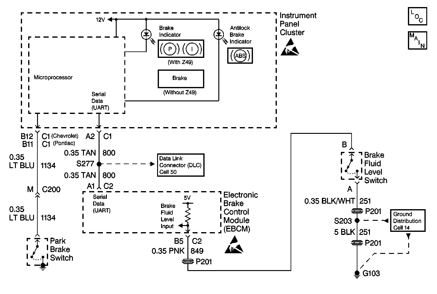
Circuit Description
The BRAKE warning indicator lamp has two functions. First, it will light whenever the park brake is set. Second, a switch built into the brake master cylinder reservoir will signal the Electronic Brake Control Module (EBCM) if the brake fluid level drops below a safe level. The EBCM will command the indicator on via serial data with the instrument cluster. In addition, the indicator is commanded on when the EBCM is initially powered up (the ignition switch is turned to the RUN position). With the ignition switch in the OFF/UNLOCK or CRANK positions (loss of EBCM serial data), the indicator will also be illuminated.
Diagnostic Aids
The following conditions will activate the brake warning indicator:
| • | An applied parking brake while the ignition switch is in the RUN position |
| • | A low fluid level in the master cylinder |
Thoroughly inspect any circuitry that may cause an intermittent complaint for the following conditions:
| • | Backed out terminals |
| • | Improper mating |
| • | Broken locks |
| • | Improperly formed or damaged terminals |
| • | Poor terminal-to-wiring connections |
| • | Physical damage to the wiring harness |
Test Description
-
This test determines if an ABS malfunction has turned the BRAKE warning indicator on.
-
This test determines if the indicator is being commanded ON by the park brake circuit.
-
This test determines if the EBCM is commanding the warning indicator ON.
-
This test checks for a park brake switch stuck in the closed position.
-
This test checks for a short to ground in the park brake switch circuit.
-
This test checks for a brake fluid level sensor stuck in the closed position.
-
This test checks for a short to ground in the brake fluid level sensor circuit.
Step | Action | Value(s) | Yes | No |
|---|---|---|---|---|
|
Important: Zero the J 39200 test leads before making any resistance measurements. Refer to the J 39200 user's manual. | ||||
1 | Was the Brake Warning System Check performed? | -- | Go to Step 2 | |
Is the amber ABS warning indicator also ON? | -- | Go to A Diagnostic System Check - ABS in ABS | Go to Step 3 | |
Does the scan tool indicate that the Park Brake Switch is APPLIED? | -- | Go to Step 5 | Go to Step 4 | |
Does the scan tool indicate that the Brake Warning Lamp Cmd is ON? | -- | Go to Step 8 | Go to Diagnostic System Check - Instrument Cluster in Instrument Panel, Console, and Gauges | |
5 | Is the park brake fully released? | -- | Go to Step 6 | Go to Step 10 |
Did the BRAKE warning indicator turn off? | -- | Go to Step 11 | Go to Step 7 | |
Is the resistance within the specified range? | OL (Infinite) | Go to Diagnostic System Check - Instrument Cluster in Instrument Panel, Console, and Gauges | Go to Step 12 | |
Did the BRAKE warning indicator turn off? | -- | Go to Step 13 | Go to Step 9 | |
Is the resistance within the specified range? | OL (Infinite) | Go to Step 14 | Go to Step 15 | |
10 | Release the park brake. Is the action complete? | -- | -- | |
11 | Replace the park brake switch. Refer to Park Brake Lever Assembly Replacement in Park Brake. Is the repair complete? | -- | -- | |
12 | Repair the short to ground in CKT 1134. Is the repair complete? | -- | -- | |
13 | Replace the master cylinder fluid level sensor. Refer to Brake Fluid Level Indicator Switch Replacement . Is the repair complete? | -- | -- | |
14 | Replace the EBCM. Refer to Electronic Brake Control Module Replacement in Antilock Brake System. Is the repair complete? | -- | -- | |
15 | Repair the short to ground in CKT 849. Is the repair complete? | -- | -- | |
