Wheel Drive Shaft Inner Joint and Boot Replacement Tripot Joint 2.2L
Disassembly Procedure
Tools Required
J 8039-A Snap Ring
Pliers
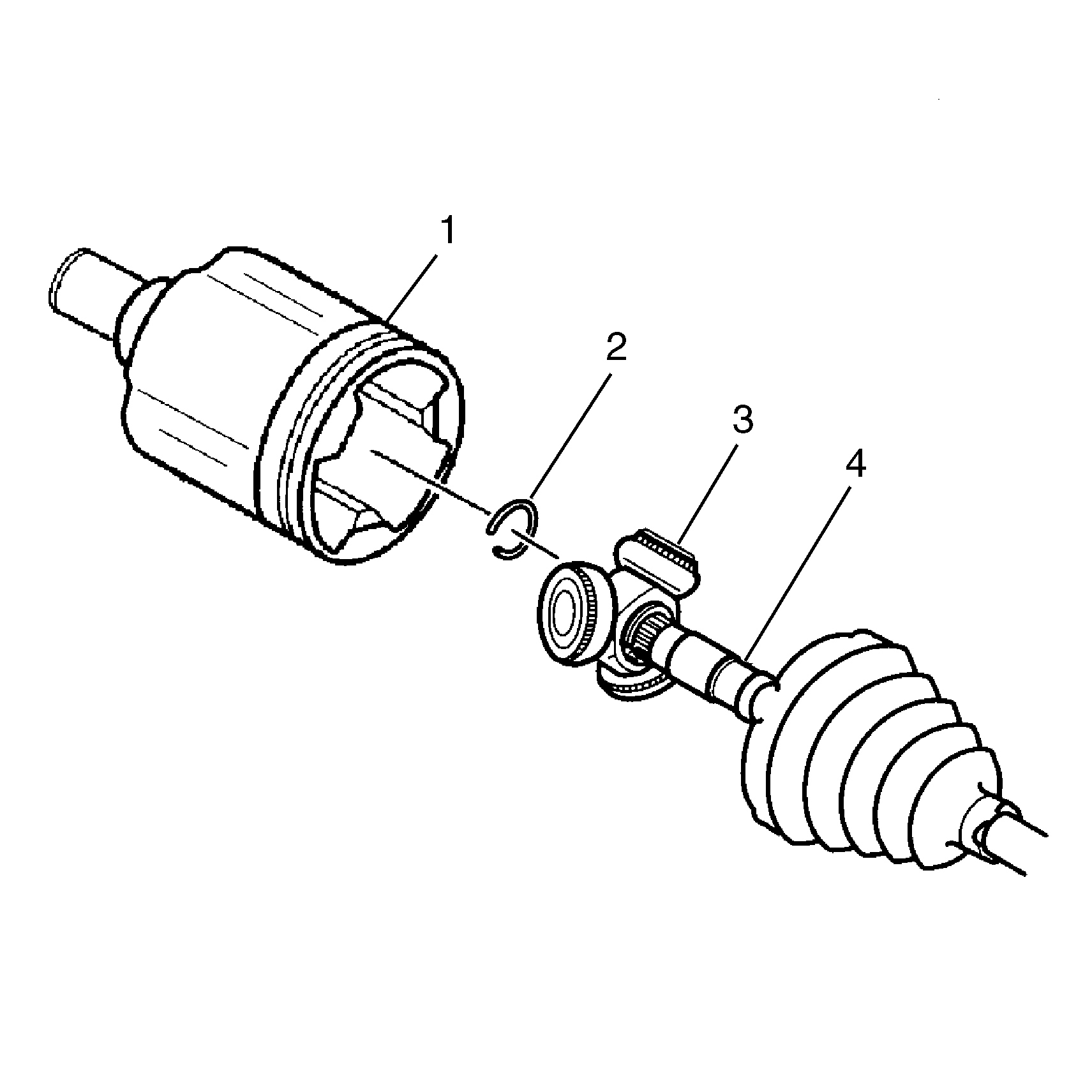
Important: Do not cut through boot and damage sealing surface of outer housing (1).
- Remove the small retaining clamp from the halfshaft bar (4) with
a side cutter. Discard the small retaining clamp.
- Remove the larger boot retaining clamp from the inboard joint
with a side cutter. Discard the boot retaining clamp.
- Separate the housing assembly (1) from the boot at large
diameter.
- Slide boot away from joint along halfshaft bar.

- Before removing the tripot
spider assembly (3) from the halfshaft bar, perform the following procedure:
Important: Never reuse the spacer ring (2).
- Remove the spacer ring (2) from the end of the halfshaft bar
using J 8039-A
.

- Place a brass drift on
the area of the tripot spider (1) next to the halfshaft bar (3).
- Tap on the brass drift with the hammer.
Important: Handle the tripot spider assembly (1) with care.
- Remove the tripot spider assembly (1) from the halfshaft bar (3).

- Remove the spacer ring (1)
from the shoulder of the halfshaft bar using J 8039-A
.
- Clean the following items thoroughly with cleaning solvent. Removing
all traces of old grease and any contaminates.
- Dry all the parts.
- Remove the boot from the halfshaft bar.
- Inspect the following parts for damage or wear:
Assembly Procedure
Tools Required
J 35910 Seal Clamp
Tool

- Install the new small
boot retaining clamp on the neck of the boot.
- Do not crimp the small boot retaining clamp.
- Clean the halfshaft bar. Use a wire brush to remove any rust in
the boot mounting area (grooves).
- Slide the tripot boot onto the halfshaft bar, passing the boot
grooves of the halfshaft bar toward the CV end of the halfshaft bar.
Important: Ensure that the spacer ring (1) is next to the shoulder of the
halfshaft bar before installing the tripot spider (3).
- Place the new spacer ring (1) next to the shoulder on the halfshaft
bar.
- Place the tripot spider assembly (3) onto the halfshaft
bar.

- Place the halfshaft assembly
onto the arbor press.
| • | The tripot spider assembly must be on the press plate. |
| • | The CV joint assembly must be under the press head. |
- Lower the arbor press head onto the CV joint assembly until the
tripot spider is next to the spacer ring. Do not exceed 4,000 lbs press
load during assembly.
- Remove the halfshaft assembly from the arbor press.

- Place the new spacer ring (2)
on the halfshaft bar groove at the end of the halfshaft bar.
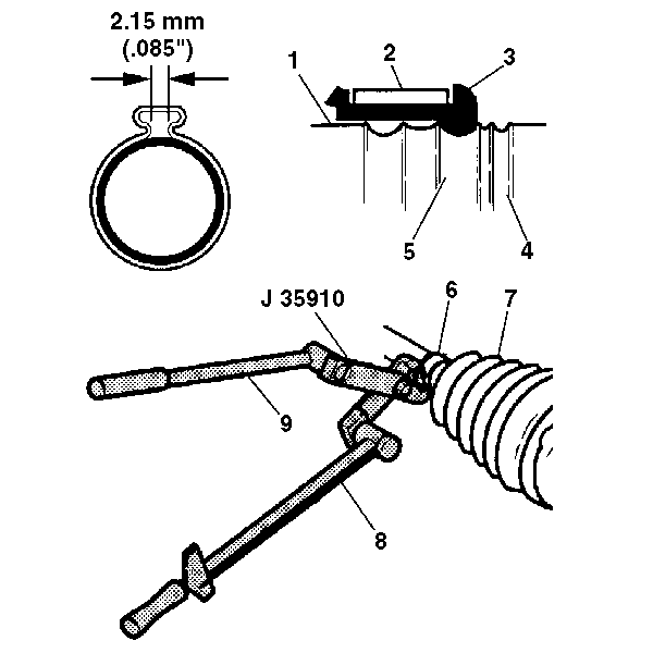
- Slide the tripot boot (7)
the corresponding groove on the halfshaft bar.
- Crimp the small boot retaining clamp (6) using J 35910
.
- Place approximately a ¼ of the grease from the service
kit in boot. Use the remainder to repack the housing.
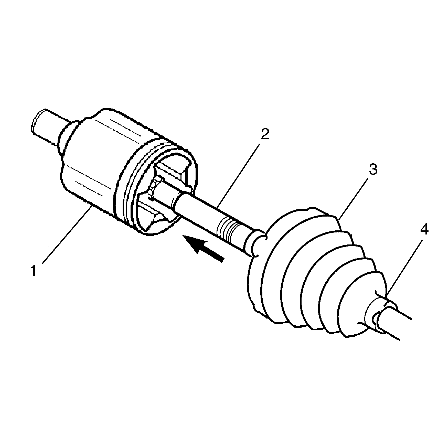
- Slide the housing (1)
over the spider assembly on the shaft (2). Engage the tripot boot.
Important: The end of the tripot boot (3) must be next to the boot stop
on the housing (1).
- Position the large boot retaining clamp around the tripot boot (3).
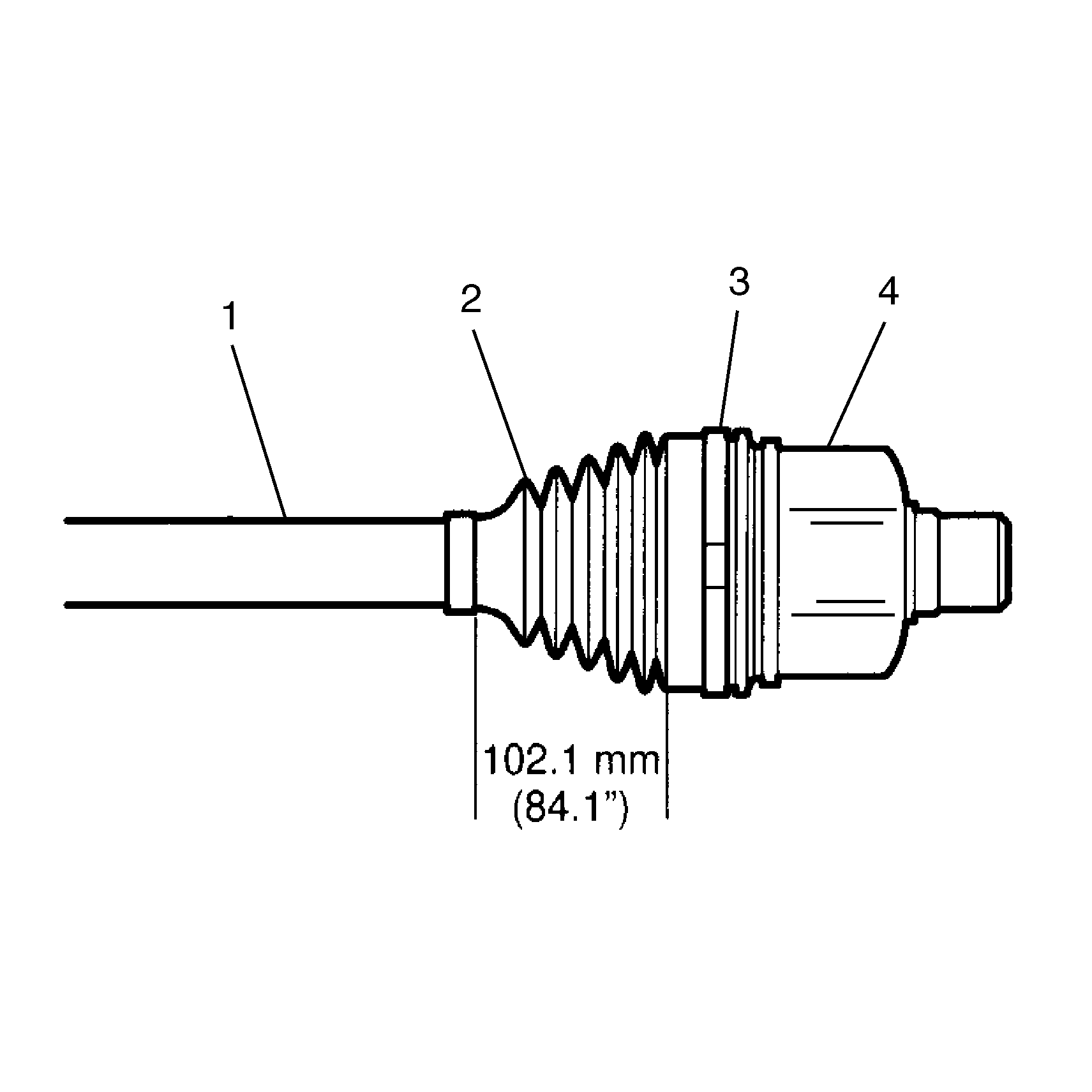
- Position joint assembly
at the proper vehicle dimension.
Important: The boot (2) must not be dimpled, stretched or out of shape in
any way. If the boot (2) is not shaped correctly, carefully equalize
pressure by disassembling and reassembling the housing (4) into the
large boot opening at proper vehicle dimension.
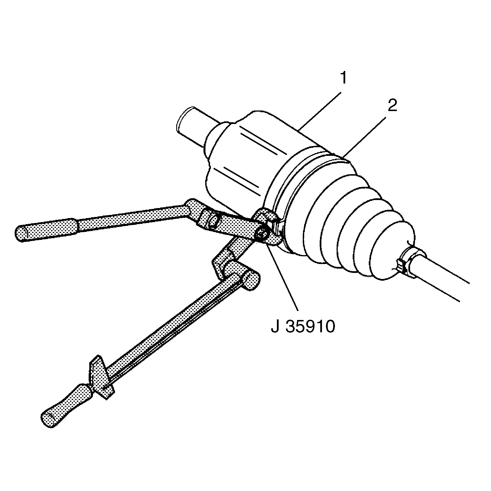
Important: Align the following items while latching:
| • | The large boot retaining clamp (2) |
- Crimp the large boot retaining clamp (2) with J 35910
.
Wheel Drive Shaft Inner Joint and Boot Replacement Free Motion Joint 2.4 L
Disassembly Procedure

Important: The transaxle stub shaft may disengage from the transaxle during halfshaft
tripot removal. If this condition occurs, transaxle fluid may leak from the
transaxle through the stub shaft location.
- Perform the following steps if the transaxle stub shaft has disengaged
into the female tripot housing on removal from transaxle.
Important: Never reuse the snap ring.
- Remove the snap ring from the stub shaft.
- Discard the snap ring.

- Connect the J 38868
to the snap ring groove on the stub
shaft and connect an J 6125-1B
to the J 38868
.
- Use the J 6125-1B
to remove the shaft from the tripot housing.
- Install new snap rings onto the stub shaft.
- Refer to the transaxle unit repair for the proper installation
of the stub shaft into the transaxle.
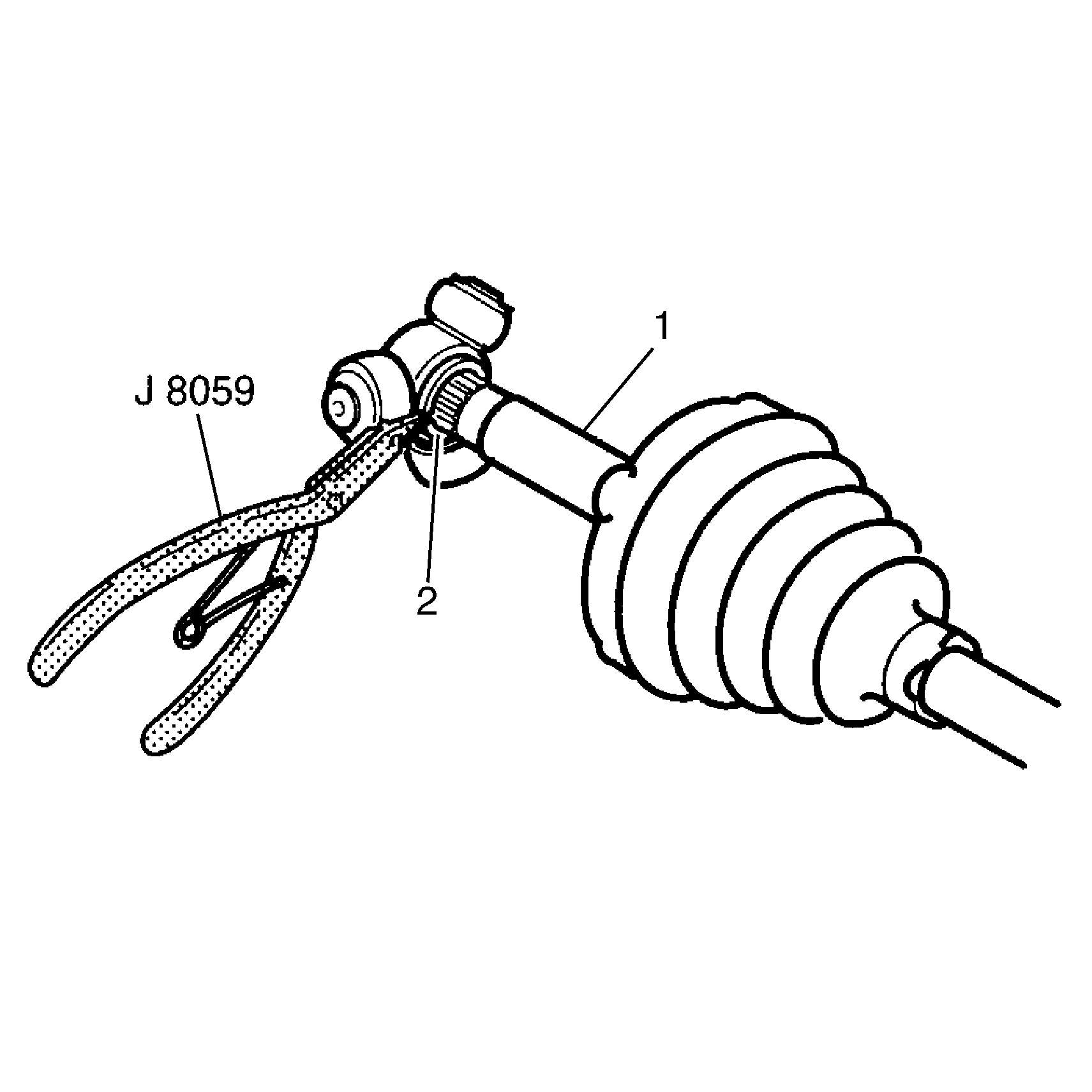
Important: Do not cut through the halfshaft inboard boot and damage sealing surface
of the outer housing and the trilobal tripot bushing.
- Remove the small boot retaining clamp from the halfshaft bar with a
side cutter.
- Discard the small boot retaining clamp.
- Remove the large boot retaining clamp from the tripot joint with
side cutter.
- Discard the large boot retaining clamp.
- Separate the tripot boot from the trilobal tripot bushing at the
large diameter.
- Slide the boot away from the joint along the halfshaft bar.
- Remove the housing from the tripot joint spider and the halfshaft
bar.
- Spread spacer ring (2) with J 8059
.
- Slide the spacer ring (2) and tripot joint spider back
on halfshaft bar (1).
- Remove the halfshaft bar retaining ring from the groove on the
halfshaft bar (1).
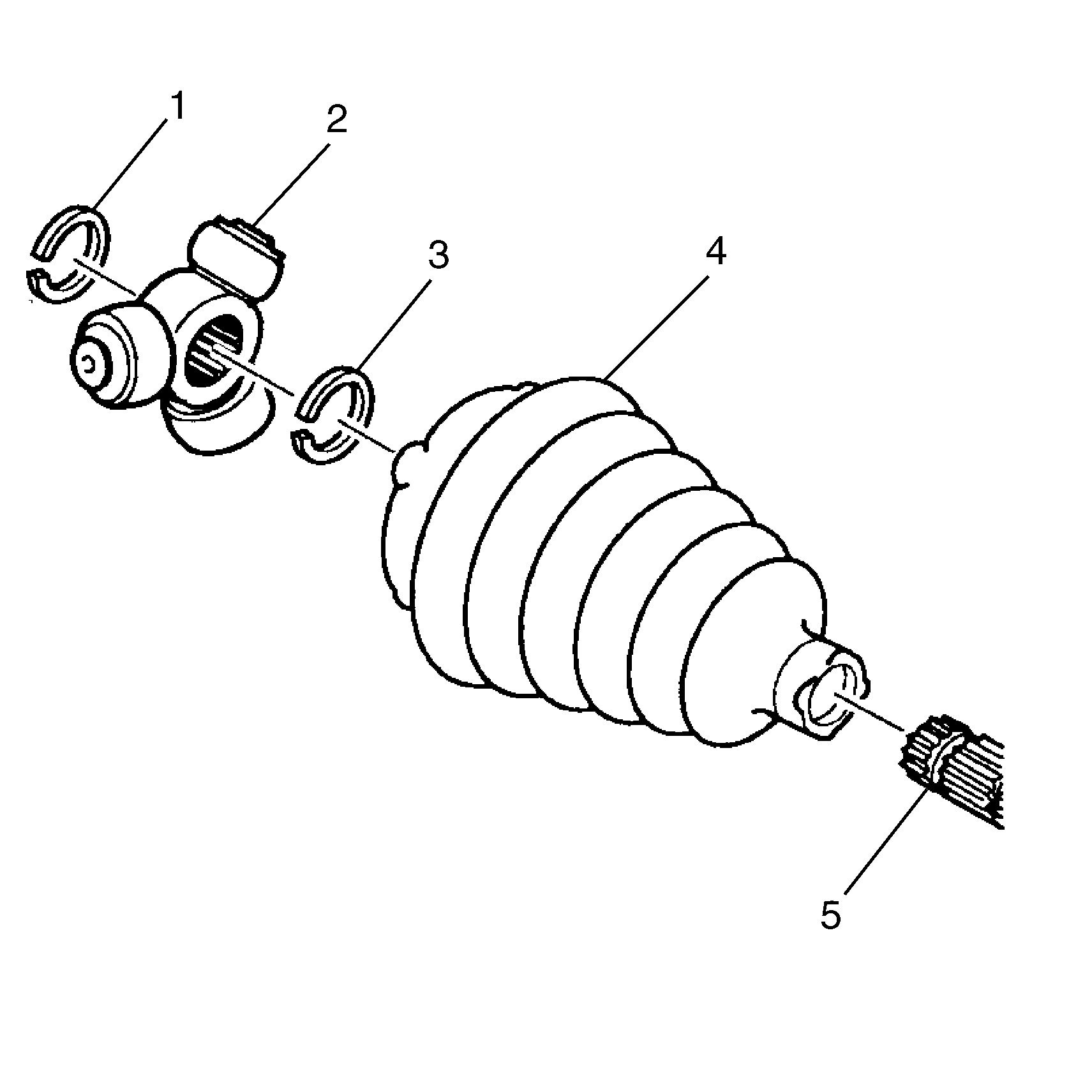
- Slide tripot joint spider
assembly off of the halfshaft bar (1).
- Clean the following items with cleaning solvent:
- Remove all traces of old grease and any contaminates. Dry all
the parts.
- Remove the trilobal tripot bushing from the housing.
- Remove the spacer ring (2) and the boot (3) from
the halfshaft bar.
- Inspect the following parts for damage or wear:
| • | The halfshaft inboard boot (3) |
| • | The tripot joint spider assembly (1) |
| • | The trilobal tripot bushing |
Assembly Procedure
Tools Required

- Install the new small
boot retaining clamp (2) on the neck of the tripot boot (1).
- Do not crimp the small boot retaining clamp.
- Clean the halfshaft bar. Use a wire brush to remove any rust in
the boot mounting area (grooves).
- Slide the tripot boot (7) onto the halfshaft bar.
Notice: Use the correct fastener in the correct location. Replacement fasteners
must be the correct part number for that application. Fasteners requiring
replacement or fasteners requiring the use of thread locking compound or sealant
are identified in the service procedure. Do not use paints, lubricants, or
corrosion inhibitors on fasteners or fastener joint surfaces unless specified.
These coatings affect fastener torque and joint clamping force and may damage
the fastener. Use the correct tightening sequence and specifications when
installing fasteners in order to avoid damage to parts and systems.
- Position the neck
of the tripot boot in the boot groove (3) on the halfshaft bar.
- Crimp the boot retaining clamp (6) using J 35910
, a breaker bar (9) and a torque
wrench (8).
Tighten
Tighten the boot retaining clamp to 136 N·m (100 lb ft).
- Check the gap dimension. Continue tightening until the gap dimension
is reached.

- Install the spacer ring (2)
on the halfshaft bar (1) and beyond the second groove.
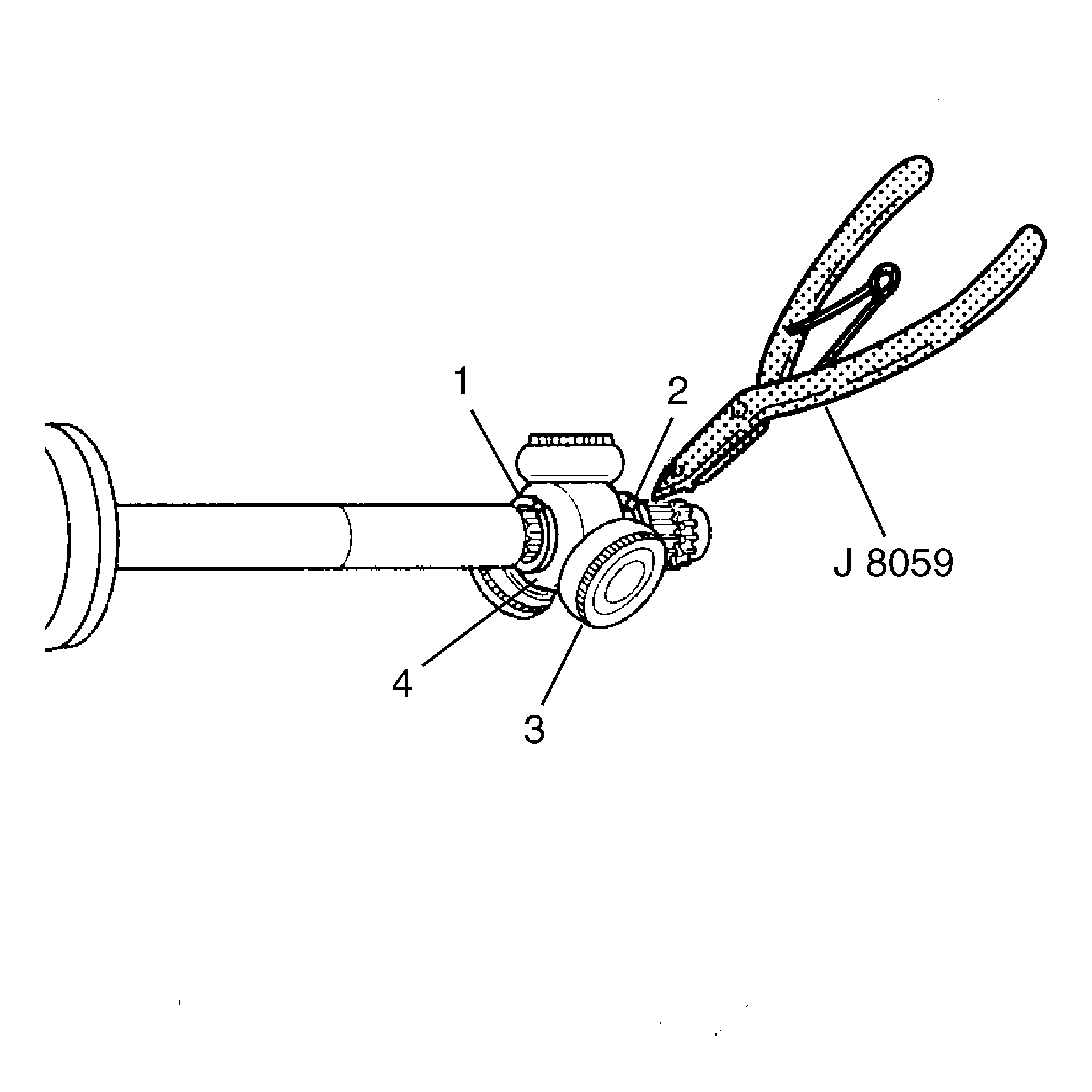
- Slide the tripot joint
spider assembly (3) toward the spacer ring as far as it will go on
the halfshaft bar.
Important: Ensure that the counterbored face of the tripot joint spider (4)
faces end of the halfshaft bar.
- Install the halfshaft bar retaining ring (2) in the groove
of the halfshaft bar using J 8059
.
- Slide the tripot joint spider assembly (3) towards the
end of the halfshaft bar.
- Reseat the spacer ring in the groove on the halfshaft bar.
- Place approximately half of the grease from the service kit in
the halfshaft inboard boot. Use the remainder of the grease to repack the
housing. Ensure the bushing is flush with the face of the housing.
- Install the trilobal tripot bushing to housing.
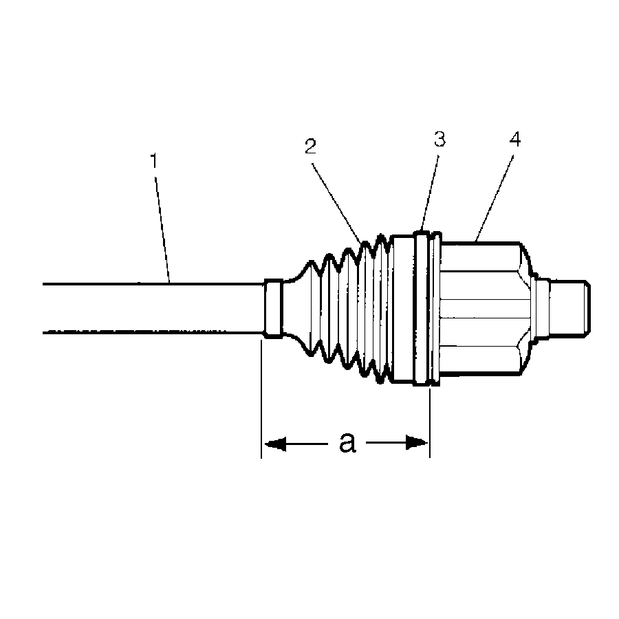
- Position the larger new
clamp (3) on the halfshaft inboard boot (2).
- Slide the housing (4) over the tripot joint spider assembly
on the halfshaft bar (1).
- Slide the large diameter of the halfshaft inboard boot (2),
with the larger clamp (3) in place, over the outside of the trilobal
tripot bushing.
- Locate the lip of the boot in the groove.
- Position the joint assembly at the proper vehicle dimension.

Important: The halfshaft inboard boot (3) must not be dimpled, stretched
out or out of shape in any way. If the halfshaft inboard boot (3) is
not shaped correctly, carefully insert a thin, flat, blunt tool (no sharp
edges) between the large boot opening and the trilobal tripot bushing to equalize
the pressure. Shape the halfshaft inboard boot (3) properly by hand.
Remove the thin, flat, blunt tool.
Important: Align the following items while latching:
| • | The halfshaft inboard boot (3) |
- Latch the boot retaining clamp (2) using J 35566
.


