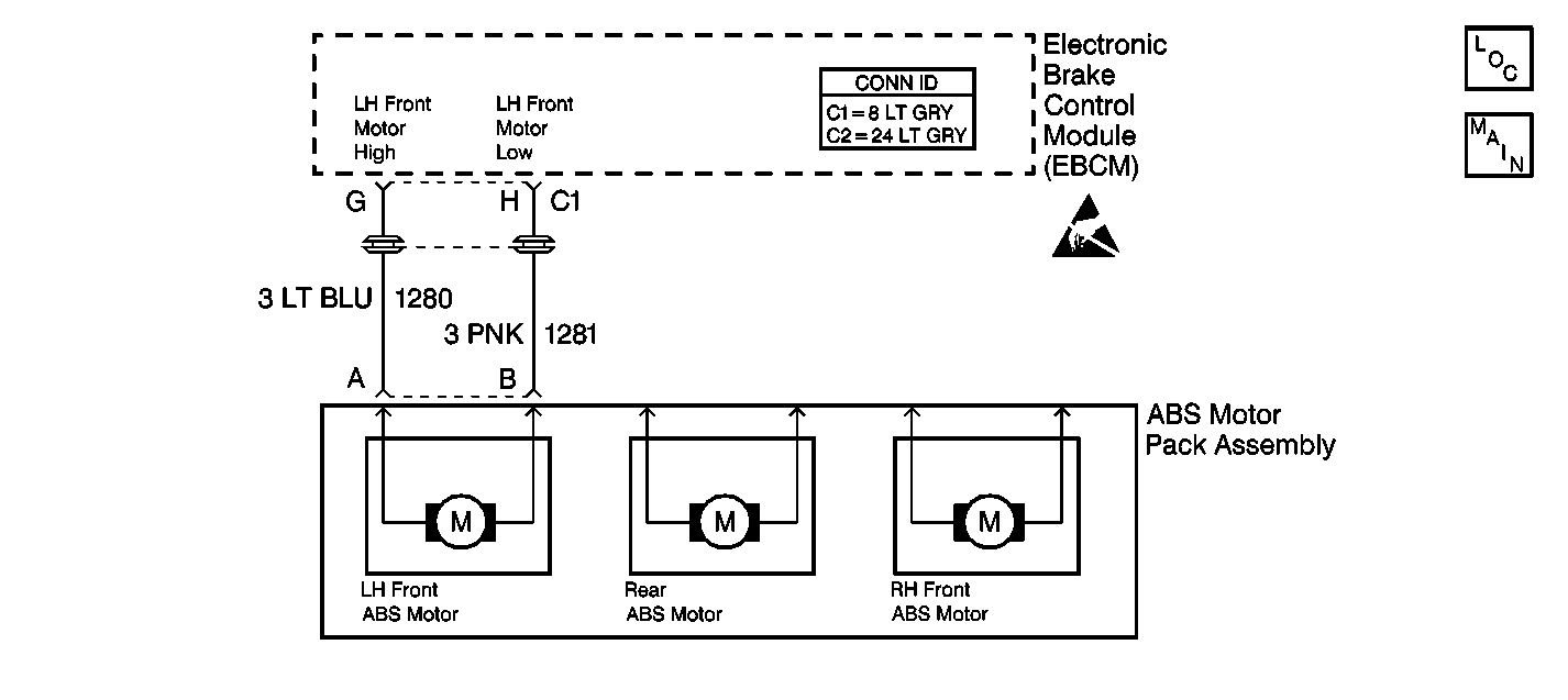
Circuit Description
DTC C1244 detects a bound-up ESB, a stuck ABS motor, or a seized brake modulator. When the release is commanded during initialization, the ESB should release the ABS motor, resulting in the sensed current being less than the commanded current (motor spins freely). If the ABS motor is not moving, sensed current will be equal to stall currents.
Conditions for Setting the DTC
DTC C1244 can set during brake motor initialization at the following speeds:
| • | 0 km/h (0 mph) when the brake is off |
| • | 5 km/h (3 mph) when the brake is on |
DTC C1244 can set during ABS stops
A malfunction exists if the EBCM detects a condition in which the EBCM cannot move the ABS motor in either direction.
Action Taken When the DTC Sets
| • | A malfunction DTC stores. |
| • | The ABS disables. |
| • | The ABS warning indicator turns on. |
Conditions for Clearing the DTC
| • | The condition responsible for setting the DTC no longer exists and the Scan Tool Clear DTCs function is used. |
| • | 100 drive cycles pass with no DTCs detected. A drive cycle consists of starting the vehicle, driving the vehicle over 16 km/h (10 mph), stopping and then turning the ignition off. |
Diagnostic Aids
The following conditions may cause an intermittent malfunction if the conditions exist in a mechanical part of the system:
| • | Sticking |
| • | Binding |
| • | Slipping |
Use the enhanced diagnostic function of the Scan Tool in order to measure the frequency of the malfunction. DTC C1244 may set after modulator disassembly if the modulator pistons are positioned at the bottom of the modulator piston bore.
Thoroughly inspect any circuitry that may be causing the intermittent complaint for the following conditions:
| • | Backed out terminals |
| • | Improper mating |
| • | Broken locks |
| • | Improperly formed or damaged terminals |
| • | Poor terminal-to-wiring connections |
| • | Physical damage to the wiring harness |
Clear the DTCs after completing the diagnosis. Test drive the vehicle for three drive cycles in order to verify that the DTC does not reset. Use the following procedure in order to complete one drive cycle:
- Start the vehicle.
- Drive the vehicle over 16 km/h (10 mph).
- Stop the vehicle.
- Turn the ignition to the OFF position.
Test Description
-
This test ensures that the motor circuits are in the proper connector cavity.
-
This test checks the ability of the motor to move by releasing hydraulic pressure to the wheel cylinders.
-
This test checks the ability of the motor to move by applying hydraulic pressure to the wheel cylinders.
-
This test checks for motor movement by comparing the feedback current to the command current during apply.
-
This test checks for a short between the motor high and the motor low circuits.
-
This test checks for a shorted motor.
-
This test determines if the malfunction is caused by the EBCM.
-
This test determines if the hydraulic modulator is functioning properly by manually moving the piston.
Step | Action | Value(s) | Yes | No | ||||||||
|---|---|---|---|---|---|---|---|---|---|---|---|---|
|
Important: Zero the J 39200 test leads before making any resistance measurements. Refer to the J 39200 user's manual. | ||||||||||||
1 | Was the ABS Diagnostic System Check performed? | -- | ||||||||||
Inspect the following connectors for the correct wire color/connector cavity combinations:
Are the correct wires located in the correct connector cavities? | -- | |||||||||||
Do not start the engine. Does the brake pedal fall? | -- | |||||||||||
Does the brake pedal rise? | -- | |||||||||||
Did the left front ABS motor feedback current momentarily drop below the specified current? | 8 A | |||||||||||
Is the resistance within the specified range? | OL (Infinite) | |||||||||||
Use the J 39200 in order to measure the resistance between the ABS brake motor pack connector terminal A and the ABS brake motor pack connector terminal B. Is the resistance within the specified range? | 0.2-1.5ohms | |||||||||||
8 |
Do any of the terminals exhibit poor terminal contact or corrosion? | -- | ||||||||||
Does DTC C1244 set during the last three ignition cycles? | -- | |||||||||||
(The ABS brake modulator left front gear is the gear that is closest to the front when the ABS brake modulator is mounted in the vehicle.) Is it possible to rotate the left front brake modulator gear at least 8.5 full revolutions from lock to lock? | -- | |||||||||||
11 | Place the wires into the correct connector cavities. Refer to Antilock Brake System Connector End Views . Is the repair complete? | -- | -- | |||||||||
12 | Repair the short between CKT 1280 and CKT 1281. Refer to Wiring Repairs in Wiring Systems. Is the repair complete? | -- | -- | |||||||||
13 | Replace the ABS motor pack. Refer to ABS Motor Pack Replacement . Is the repair complete? | -- | -- | |||||||||
14 | Replace the brake modulator. Refer to Brake Modulator Replacement . Is the repair complete? | -- | -- | |||||||||
15 | Replace the terminals that exhibit signs of poor terminal contact or corrosion. Is the repair complete? | -- | -- | |||||||||
16 | Replace the EBCM. Refer to Electronic Brake Control Module Replacement . Is the repair complete? | -- | -- | |||||||||
17 | The malfunction is intermittent or is not present at this time. Refer to Diagnostic Aids for more information. Is the action complete? | -- | System OK | -- | ||||||||
