THROTTLE LINKAGE REVISIONS TO REDUCE PEDAL EFFORT

SUBJECT: 8.2L THROTTLE LINKAGE REVISIONS
MODELS: 1981 and PRIOR C6, C7, B6 MODELS W/8.2L DIESEL ENGINE
Effective with SOP 1982, 8.2L powered models will include revised throttle linkage components to reduce pedal effort and improve pedal height.
The following details the installation requirements for linkage kit P/N 8884272 which contains these revised components:
Description Part Number --------------- ------------- Cab Lever 2081355 Gov. Spring-Inner 2086658 Gov. Spring-Outer 2086640 Modulator Spring 717225 Rod Asm. 2091924 Bellcrank Asm. 2091925 Gov. Lever 2091926 Bellcrank Brkt. 2091927
SERVICE PROCEDURE
1. Disconnect battery.
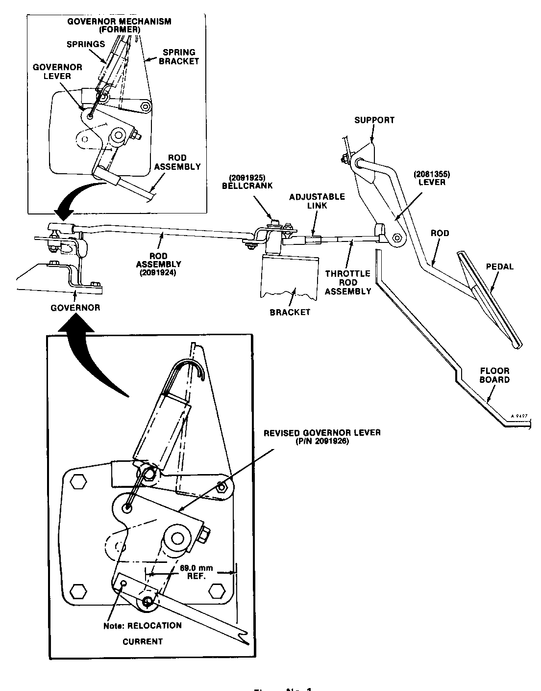
2. Remove existing throttle components including (see Figure No. 1):
A. Rod Assembly
B. Bellcrank
C. Throttle Rod Assembly
D. Lever
E. Springs (replacement required on trucks prior to VIN GMC 1GDG7D1F1BV595513 and Chev. 1GBJ7D1F6BV139537 only). Springs requiring replacement are red in color.
F. Bracket
3. Disconnect automatic transmission modulator cable.
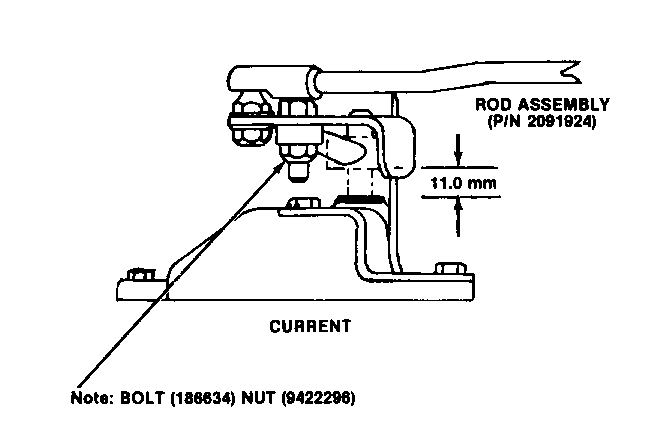
4. Proper positioning of governor fuel lever is essential in obtaining correct throttle action. A governor cover retaining bolt (see Figure No. 2) should be sighted directly below the existing lever attachment hole. The 69.0 mm (2.7 in.) dimension should be maintained when positioning the lever on the governor shaft. An 11 mm (.43 in.) height should be maintained above the governor cover (see Figure No. 2). Install the governor lever (P/N 2091926 and secure with bolt (P/N 186634) and nut (P/N 9422296).
5. Replace the throttle lever with P/N 2081355.
6. Install bellcrank bracket, P/N 2091927.
7. Install bellcrank, P/N 2091925.
8. Re-install the removed throttle rod assembly and adjust linkage as follows:
A. Depress accelerator pedal to floor.
B. Rotate governor lever to wide open throttle.
1. Manual Transmission: Adjust throttle rod assembly so that it is approximately 12.0 mm (.47 in.) beyond direct engagement with bell-crank attachment hole.
2. Automatic Transmission: Adjust throttle rod assembly so that it is approximately 20.0 mm (.79 in.) beyond direct engagement with bell- crank attachment hole.
C. Assemble throttle rod in bell-crank.
9. Reconnect transmission modulator cable. Replace existing cable return spring with P/N 717225 (white in color).
10. Install inner and outer throttle retum springs P/N's 2086640 (grey in color) and 2086658 (grey in color).
11. Check to assure wide open throttle just as accelerator pedal reaches floor. Check transmission modulator cable travel for free extension and return.
12. Reconnect battery.


General Motors bulletins are intended for use by professional technicians, not a "do-it-yourselfer". They are written to inform those technicians of conditions that may occur on some vehicles, or to provide information that could assist in the proper service of a vehicle. Properly trained technicians have the equipment, tools, safety instructions and know-how to do a job properly and safely. If a condition is described, do not assume that the bulletin applies to your vehicle, or that your vehicle will have that condition. See a General Motors dealer servicing your brand of General Motors vehicle for information on whether your vehicle may benefit from the information.
