CAMPAIGN: STEERING GEAR ARM (CONTROL ARM MAY FAIL)

Subject: PRODUCT SAFETY CAMPAIGN 85C26(a) STEERING CONTROL ARM MAY FAIL
Model and Year: 1982-1985 CHEVROLET C70 MEDIUM DUTY CONVENTIONAL MODEL TRUCKS EQUIPPED WITH 8.2L DIESEL ENGINES (RPO LH3 & LH4) AND COLEMAN FRONT DRIVE AXLES SEO IFVQ 12,000 LB. CAPACITY OR IFVZ 9,000 LB. CAPACITY AND AIR BRAKES (RPO JE4) OR HYDRAULIC BRAKES (RPO JE3)
The following information supplements Campaign Bulletin 85C26, issued August, 1986:
SECTION III REPAIR PROCEDURE 9,000 LB. FRONT AXLE SEO IFVZ EQUIPPED WITH HYDRAULIC BRAKES JE3
The parts kit #15559733 for hydraulic brake equipped vehicles is not currently available to repair the subject vehicles.
Owners of hydraulic brake equipped vehicles will be notified of the campaign release and their involvement. In addition, the vehicle owner will be informed that parts will be available August 31, 1986. Until these parts become available, Chevrolet is providing a Service Inspection Procedure to be performed on a no charge basis on the subject hydraulic brake equipped trucks brought into Chevrolet dealerships. The letter to involved owners recommends the owner, the owner's mechanic, or a Chevrolet dealer inspect the steering arm to determine if cracks have developed. If cracks are discovered, the steering arm must be replaced.
If a vehicle is used in an off road severe heavy duty application, it is recommended the steering control arm be inspected on a weekly basis. If a vehicle is used primarily on road and not in a severe application, inspection of the steering control arm should be made at 2,000 mile intervals or at least monthly.
SERVICE PROCEDURE
INSPECTION
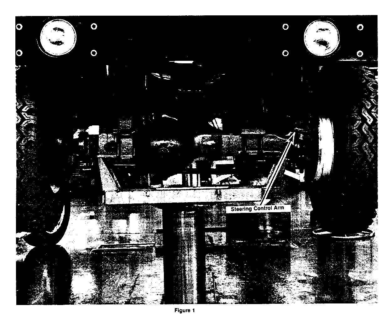
Figure #1 shows the location of the steering control arm on the Coleman front axle. It is located on the driver's side of the vehicle at the end of and on top of the axle bolted to the brake backing plate.
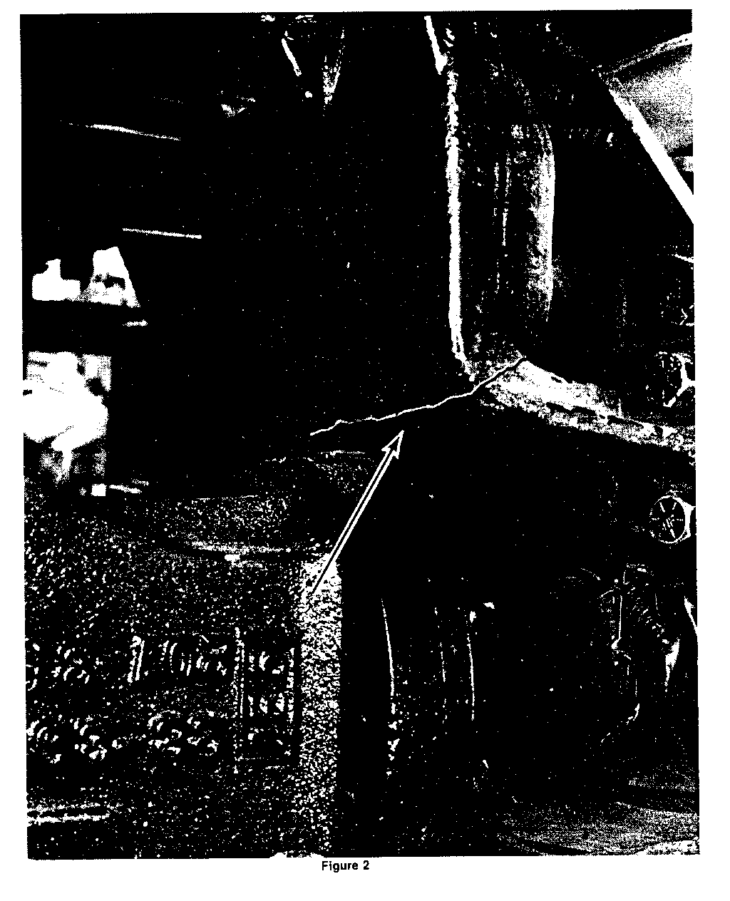
Figure #2 is a picture of the steering control arm. The arrows indicate the point at which cracks can develop. Clean the control arm with a wire brush and suitable solvent. Inspect the areas indicated for cracks. If cracks are evident, the steering control arm must be replaced.
STEERING CONTROL ARM REPLACEMENT
Notice: Torque values must be used as specified during reassembly to assure proper retention of all parts.
STEERING ARM REMOVAL
Remove the cotter pin from the drag link ball stud at the steering arm, and remove the ball stud nut.
Install puller J-26813-B and remove drag link ball stud.
Remove the four bolts which attach the left hand steering arm to the backing plate.
Remove and discard the steering arm.
INSTALLATION
Attach the new steering arm to the brake backing plate using the existing hardware. Torque the four bolts 95-105 lbs.Ft. (130-140 N.M).
Seat the drag link ball stud to the new steering arm.
Install the ball stud nut and torque 125-150 lbs.Ft. (170-205 N.M). Advance the nut to the nearest cotter pin slot and install a new cotter pin, P/N 11076431. Never back the nut off to install the cotter pin.
PARTS INFORMATION
Parts are to be obtained from the General Motors Warehousing and Distribution Division (GMWDD). To ensure these parts will be obtained as soon as possible, they should be ordered from GMWDD on a C.I.O. order with no special instruction code, but on an advise code (2).
Part Number Description Quantity ----------- ------------ -------- 15553587 Steering Arm 1 11076431 Cotter Pin 1
WARRANTY CLAIM INFORMATION
FAILED PARTS LABOR LABOR REPAIR PERFORMED PC PART NO. ALLOW FC OP HRS -------------------------------- -- ------- ----- --- ----- ----- INSPECT STEERING ARM FOR CRACKS 00 T7270 .2
INSPECT STEERING ARM FOR CRACKS REPLACE STEERING ARM 1 15553587 ** 00 T7275 .8
**The Parts Allowance is the current GMWDD Dealer Net plus 30%.
Dealers will be notified when parts kits for hydraulic brake equipped vehicles become available. At that time, dealers must contact vehicle owners and advise them that the parts kits are available, and to bring their vehicles to the dealership to be campaigned.


General Motors bulletins are intended for use by professional technicians, not a "do-it-yourselfer". They are written to inform those technicians of conditions that may occur on some vehicles, or to provide information that could assist in the proper service of a vehicle. Properly trained technicians have the equipment, tools, safety instructions and know-how to do a job properly and safely. If a condition is described, do not assume that the bulletin applies to your vehicle, or that your vehicle will have that condition. See a General Motors dealer servicing your brand of General Motors vehicle for information on whether your vehicle may benefit from the information.
