Removal Procedure
- Disconnect the negative battery cable.
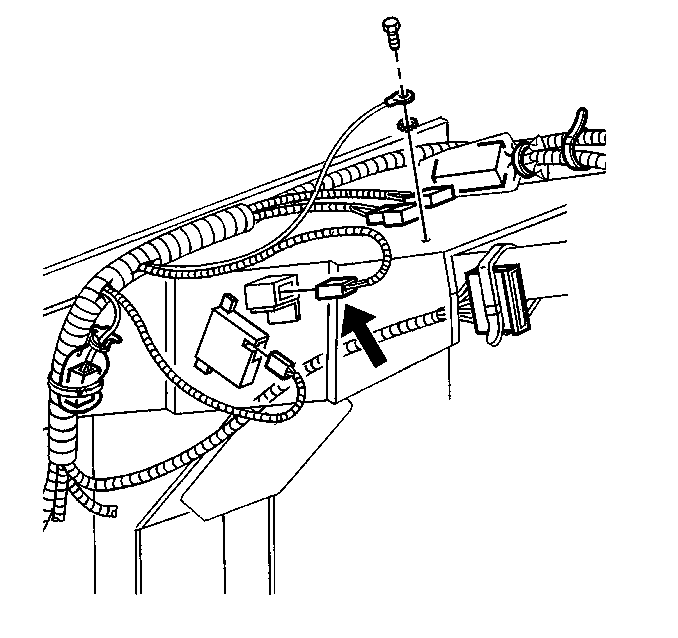
- Disconnect the DRL diode module electrical connector.
- Remove the DRL diode module screw and the DRL diode module from the steering column support.
Caution: Unless directed otherwise, the ignition and start switch must be in the OFF or LOCK position, and all electrical loads must be OFF before servicing any electrical component. Disconnect the negative battery cable to prevent an electrical spark should a tool or equipment come in contact with an exposed electrical terminal. Failure to follow these precautions may result in personal injury and/or damage to the vehicle or its components.
Installation Procedure
- Install the DRL diode module to the steering column support with the DRL diode module screw.
- Connect the DRL diode module electrical connector.
- Connect the negative battery cable.
Caution: Unless directed otherwise, the ignition and start switch must be in the OFF or LOCK position, and all electrical loads must be OFF before servicing any electrical component. Disconnect the negative battery cable to prevent an electrical spark should a tool or equipment come in contact with an exposed electrical terminal. Failure to follow these precautions may result in personal injury and/or damage to the vehicle or its components.
