Removal Procedure
- Disconnect the negative battery cable. Refer to
Caution: Unless directed otherwise, the ignition and start switch must be in the OFF or LOCK position, and all electrical loads must be OFF before servicing any electrical component. Disconnect the negative battery cable to prevent an electrical spark should a tool or equipment come in contact with an exposed electrical terminal. Failure to follow these precautions may result in personal injury and/or damage to the vehicle or its components.
. - Drain the fuel from the tank. Refer to Fuel Tank Draining in Engine Controls.
- Raise the vehicle. Refer to
Notice: When you are jacking or lifting a vehicle at the frame side rails or other prescribed lift points, be certain that the lift pads do not contact the catalytic converter, the brake pipes or the fuel lines. If such contact occurs, vehicle damage or unsatisfactory vehicle performance may result.
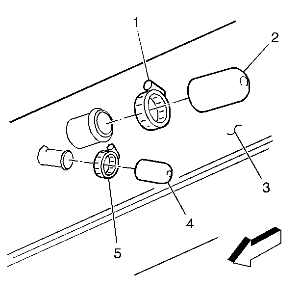
. - Loosen the filler neck hose clamps (1), (5) at the fuel tank (3). Then disconnect the fuel tank filler neck hoses from the fuel tank.
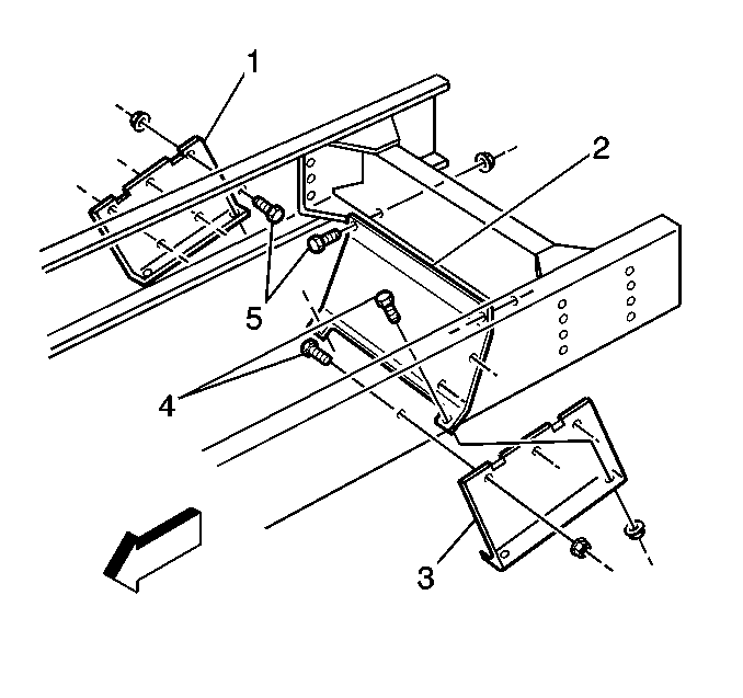
- Remove the fuel tank shields (1), (2), and (3).
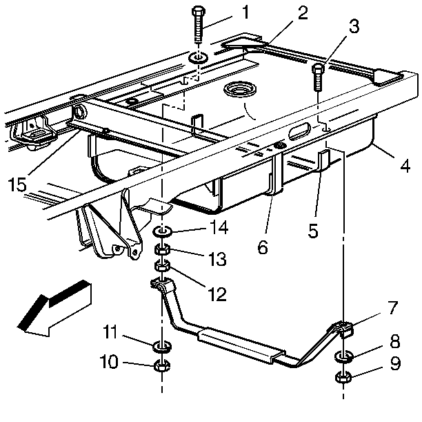
- Support the fuel tank (4) and remove the tank straps (6), (7) and insulator strips (5).
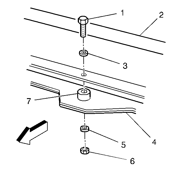
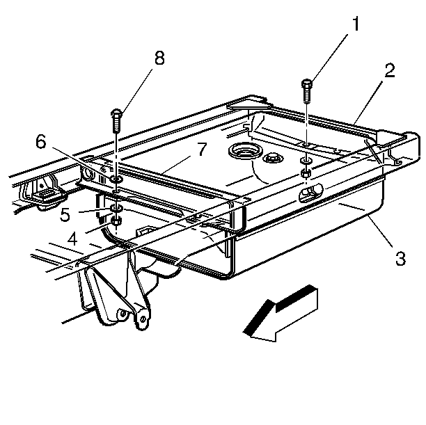
- Remove the fasteners (1), (6) to the front fuel tank crossmember spacers (7).
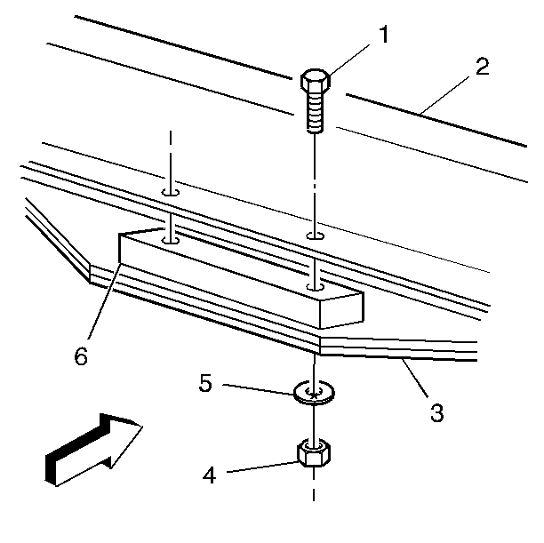
- Remove the fasteners (1), (4) to the rear fuel tank crossmember spacers (6).
- Move the fuel tank (3) to one side to remove it from the frame rail. Lower fuel tank slightly and move fuel tank to the opposite side to remove it from the frame rail. Center and lower the fuel tank.
- Disconnect the fuel feed and vapor hoses.
- Disconnect the electrical connections at the sender.
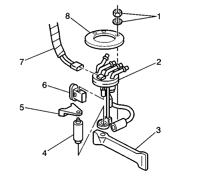
- Remove the locking ring nuts/washers (1) and lock ring (8) from the top of the fuel sending assembly (2) lift the sender assembly up from the tank flange. Refer to Fuel Sender Assembly Replacement .
Important: This vehicle is equipped with a right hand or left hand fuel tank filler. The opposite side of this 80 gallon fuel tank is plugged.
Installation Procedure
- Insert a new O-ring seal. Install the fuel sender assembly (2) into the fuel tank.
- Align fuel sender (2) with the alignment tab in tank, install locking ring (8) and nuts/washers (1).
- Raise the tank (3) slightly and reconnect the fuel feed and vapor hoses and the electrical connections at the sender.
- Raise and position the fuel tank onto one side of the frame rail. Slowly raise the fuel tank and position it onto the opposite side frame rail. Move the fuel tank to position it correctly.
- Install the fasteners (1), (4) to the rear fuel tank crossmember spacers (6).
- Install the fasteners (1), (6) to the front fuel tank crossmember spacers (7).
- Install the fuel tank straps (6), (7) and insulator strips (5).
- Install the fuel tank shields (1), (2), and (3).
- Install the fuel tank filler neck hoses to the fuel tank. Tighten the clamps (1), (5).
- Replenish the fuel in the tank. Reinstall the fuel tank filler cap.
- Reconnect the negative battery cable. If a memory retention device was not used, please reset (to the extent possible) all devices that lost their memory after the battery was disconnected.
- Check for fuel leaks.

Tighten
Tighten the lock ring nuts to 11.5 N·m (100.90 lb
in).

Notice: Use the correct fastener in the correct location. Replacement fasteners must be the correct part number for that application. Fasteners requiring replacement or fasteners requiring the use of thread locking compound or sealant are identified in the service procedure. Do not use paints, lubricants, or corrosion inhibitors on fasteners or fastener joint surfaces unless specified. These coatings affect fastener torque and joint clamping force and may damage the fastener. Use the correct tightening sequence and specifications when installing fasteners in order to avoid damage to parts and systems.

Tighten
Tighten the rear spacer nuts to 70 N·m (52 lb ft).

Tighten
Tighten the front spacer nuts to 70 N·m (52 lb ft).
Important: Tighten the strap nuts by steps, alternating between the four nuts, until the specified torque is reached. A failure to tighten the strap nuts as specified will cause the bottom of the tank to flex upward. This will result in the fuel gauge indicating that there is fuel remaining in the tank when the tank runs dry.

Tighten
Tighten the strap nuts to 58 N·m (43 lb ft).

Tighten
Tighten the shield nuts to 37 N·m (27 lb ft).

Tighten
Tighten the clamps to 3 N·m (27 lb in).
| 12.1. | Turn ON the ignition switch for 2 seconds. |
| 12.2. | Turn OFF the ignition switch for 10 seconds. |
| 12.3. | Again, turn the ignition switch to the ON position. |
| 12.4. | Check for fuel leaks. |
