Front Brake Hose Replacement Commercial FL7 and FL9
Caution: Always use double walled steel brake pipe when replacing brake pipes. Always use the correct fasteners and the original routing when replacing brake pipes. Failure to properly route and fasten brake pipes may cause brake system failure.
Important: Maintain a 6 mm (1/4 in) clearance between parallel brake pipes.
Removal Procedure
- Clean the hose fittings at both ends. Remove all dirt, grease, and foreign material.
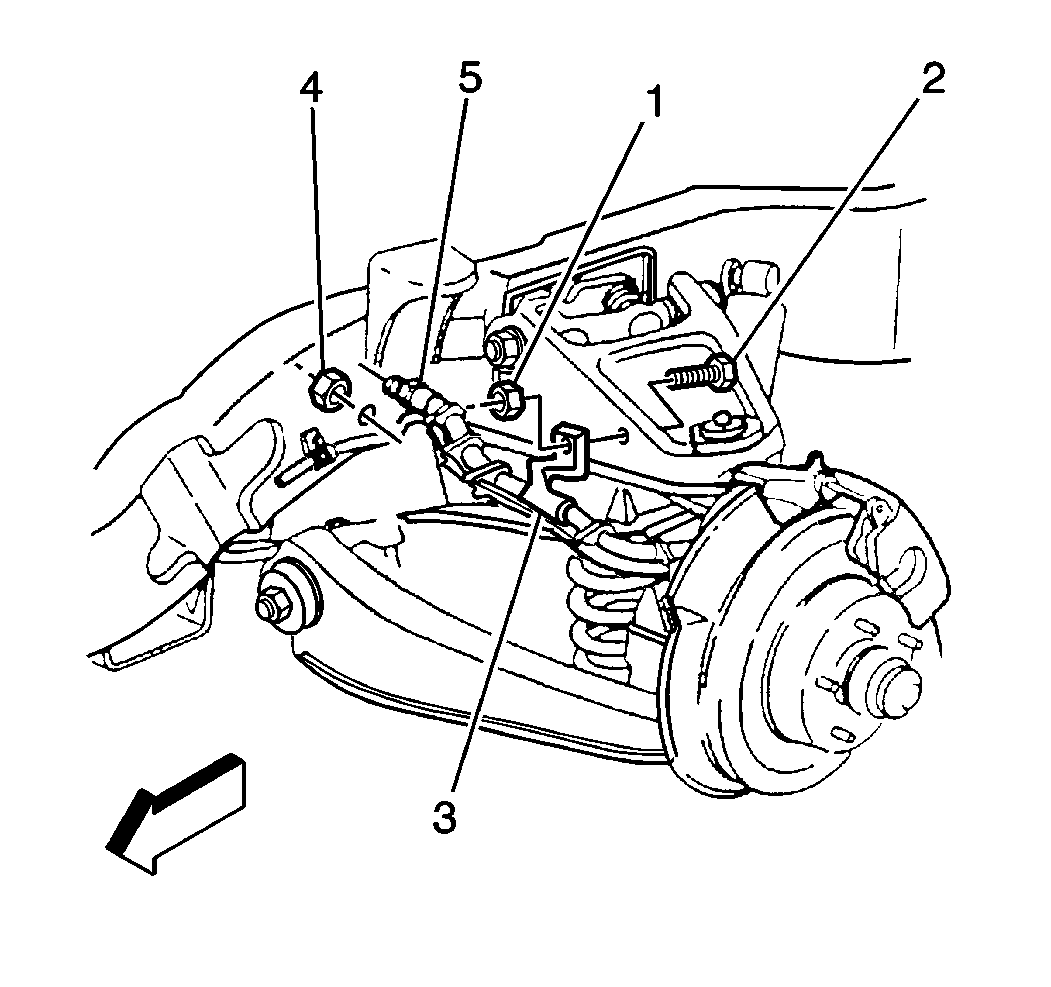
- Disconnect the pipe from the frame fitting and remove the hose nut (4).
- Remove the hose bracket nut (1) and remove the hose from the support bracket (3).
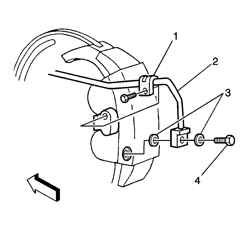
- Remove the bolt (4).
- Remove the gaskets (3).
- Remove the hose bracket nut.
- Remove the hose (2). Separate the hose from the wheel speed sensor cable, if applicable.
Installation Procedure
- Position the hydraulic fitting (2).
- Install the new brass gaskets (3).
- Install the bolt (4).
- Install the support bracket (1) bolt.
- Clip the hose to the wheel speed sensor cable. Secure the cable to the support bracket (3) with the bolt (2) and nut (1).
- Secure the hose to the frame fitting with the nut (4) and connect the pipe.
- Bleed the brake system. Refer to Hydraulic Brake System Bleeding .

Important: Use new brass gaskets.
Notice: Use the correct fastener in the correct location. Replacement fasteners must be the correct part number for that application. Fasteners requiring replacement or fasteners requiring the use of thread locking compound or sealant are identified in the service procedure. Do not use paints, lubricants, or corrosion inhibitors on fasteners or fastener joint surfaces unless specified. These coatings affect fastener torque and joint clamping force and may damage the fastener. Use the correct tightening sequence and specifications when installing fasteners in order to avoid damage to parts and systems.
Tighten
Tighten the bolt to 44 N·m (32 lb ft.).
Tighten
Tighten the bolt to 18 N·m (13 lb ft).

Tighten
Tighten the nut to 18 N·m (13 lb ft).
Important: The hose must not be twisted. The hose must not contact any suspension components.
Tighten
| • | Tighten the nut (4) to 9 N·m (80 lb in) for FL7 units with four-wheel disc brakes. |
| • | Tighten the nut (4) to 10 N·m (84 lb in) for all other units. |
Front Brake Hose Replacement Commercial FK4/FK5 and JF9
Caution: Always use double walled steel brake pipe when replacing brake pipes. Always use the correct fasteners and the original routing when replacing brake pipes. Failure to properly route and fasten brake pipes may cause brake system failure.
Important: Maintain a 6 mm (1/4 in) clearance between parallel brake pipes.
Removal Procedure
- Clean the hose fittings at both ends. Remove all dirt, grease, and foreign material.
- Disconnect the pipe at the frame fitting.
- Remove the nut to dislodge the hose.
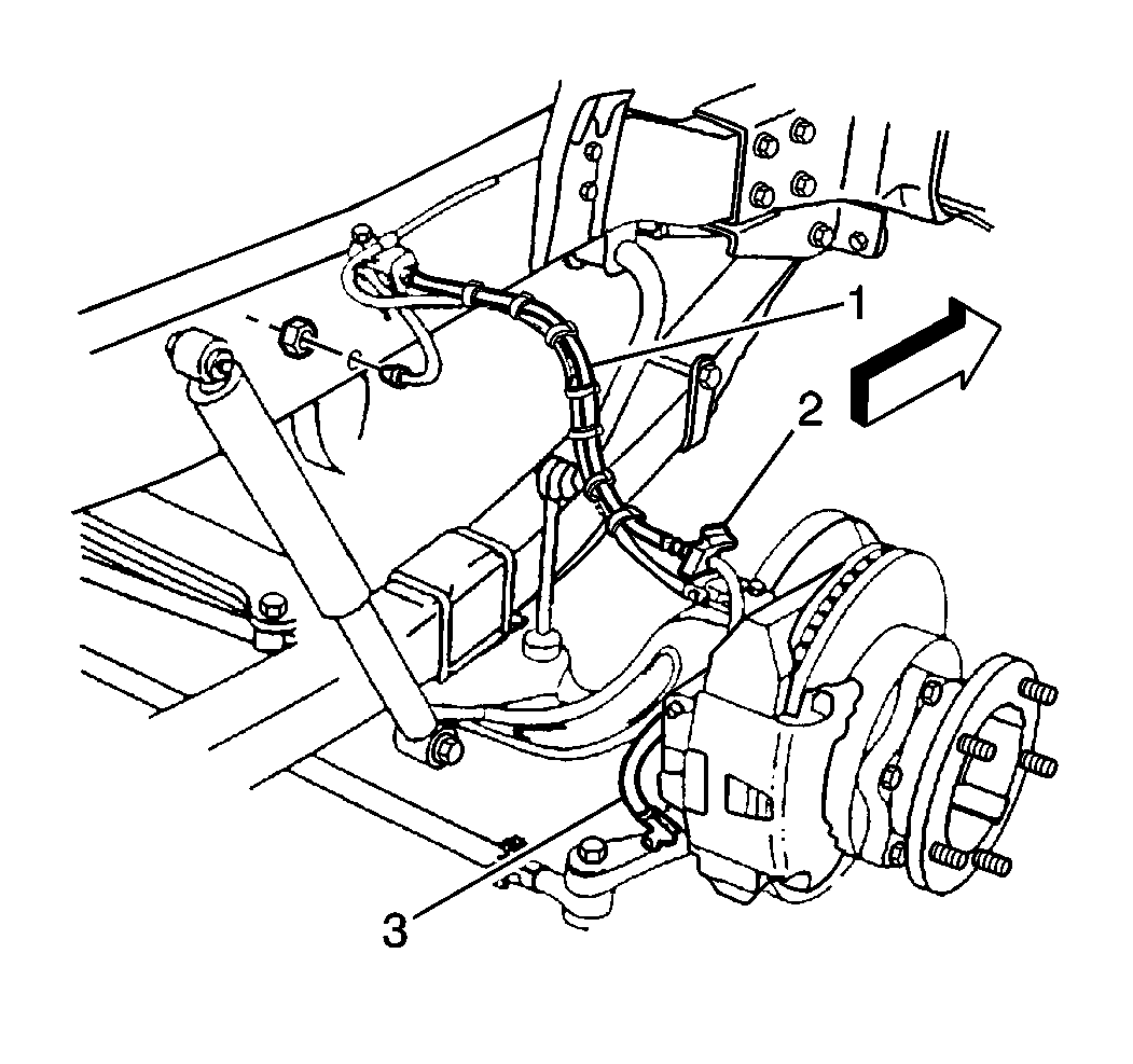
- Remove the retainer from the frame bracket. Unclip the hose (1) from the wheel speed sensor cable.
- Remove the caliper support bracket retainer (2) and dislodge the hose from this bracket.
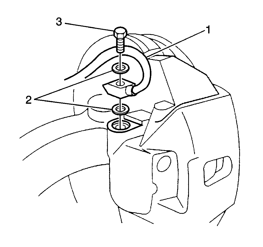
- Remove the bolt (3) in order to disconnect the fitting from the caliper (FK4 configuration shown; FK5,and JF9 similar).
- Remove the gaskets (2).
- Remove the hose (1).
Installation Procedure
- Position the fitting to the caliper (FK4 configuration shown; FK5 and JF9 similar).
- Install the new brass gaskets (2).
- Install the bolt (3).
- Position the hose into the caliper support bracket. Secure the hose with the retainer (2).
- Clip the hose to the wheel speed sensor cable.
- Insert the hose into the frame support bracket and fasten the hose with the retainer.
- Install the hose into the frame and secure the hose with the nut.
- Connect the pipe.
- Bleed the brake system. Refer to Hydraulic Brake System Bleeding .

Important: Use new brass gaskets.
Notice: Use the correct fastener in the correct location. Replacement fasteners must be the correct part number for that application. Fasteners requiring replacement or fasteners requiring the use of thread locking compound or sealant are identified in the service procedure. Do not use paints, lubricants, or corrosion inhibitors on fasteners or fastener joint surfaces unless specified. These coatings affect fastener torque and joint clamping force and may damage the fastener. Use the correct tightening sequence and specifications when installing fasteners in order to avoid damage to parts and systems.
Tighten
Tighten the bolt to 44 N·m (32 lb ft).

Important: The hose must not be twisted. The hose must not contact any suspension components.
Tighten
Tighten the nut to 10 N·m (84 lb in).
Front Brake Hose Replacement Comm. FL5/6 JB7/8Mtrhome JB8
Caution: Always use double walled steel brake pipe when replacing brake pipes. Always use the correct fasteners and the original routing when replacing brake pipes. Failure to properly route and fasten brake pipes may cause brake system failure.
Important: Maintain a 6 mm (1/4 in) clearance between parallel brake pipes.
Removal Procedure
- Clean the hose fittings at both ends. Remove all dirt, grease, and foreign material.
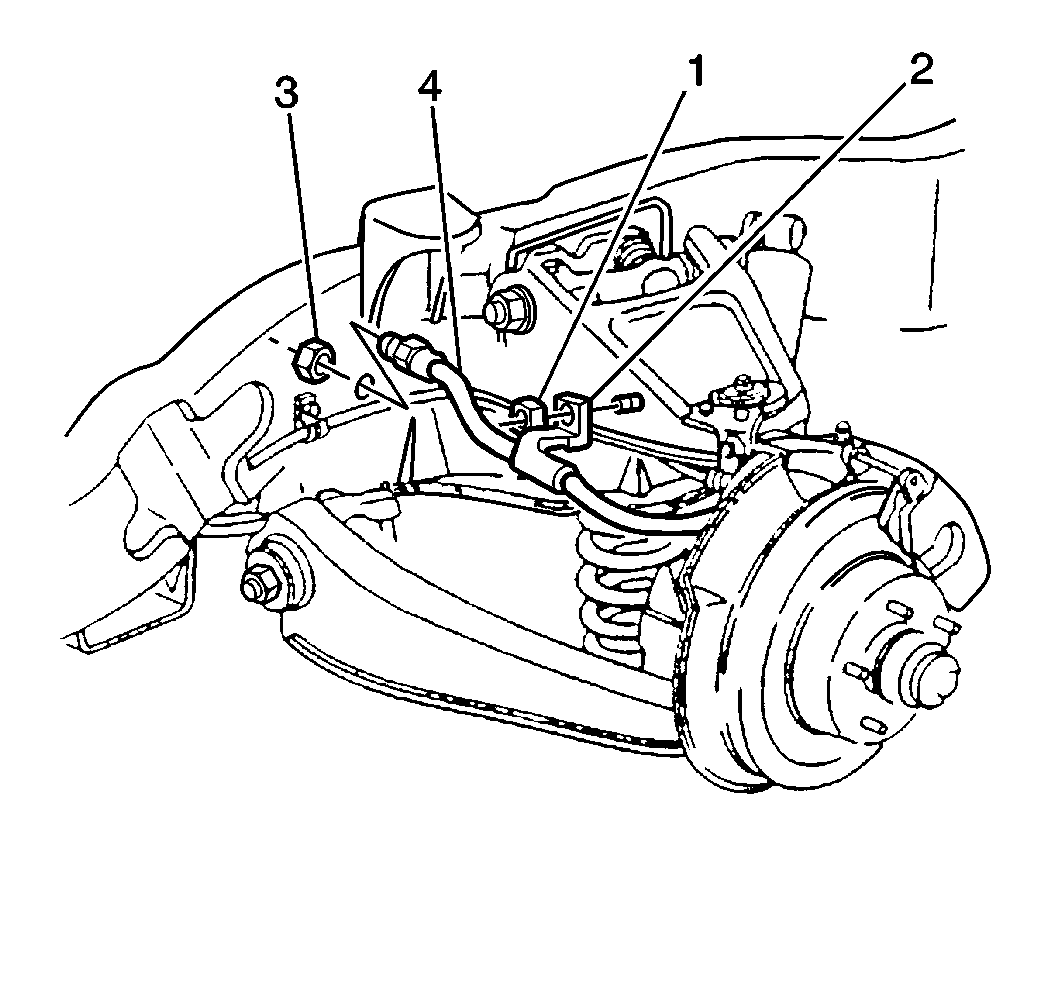
- Disconnect the pipe from the frame fitting and remove the hose nut (3).
- Remove the hose bracket nut (1) and remove the hose from the support bracket (2).
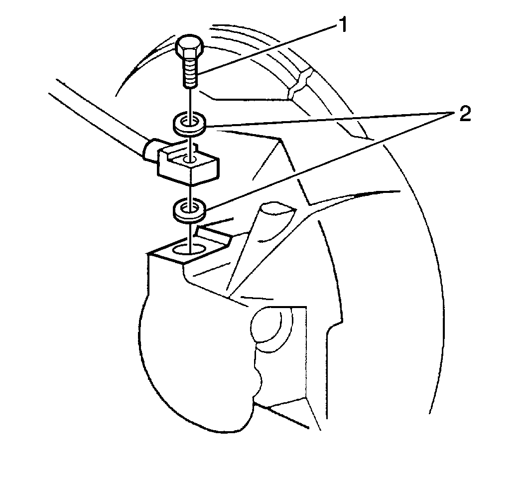
- Remove the bolt (1).
- Remove the gaskets (2).
- Remove the hose. Separate the hose from the wheel speed sensor cable, if applicable.
Installation Procedure
- Install the fitting.
- Install the new brass gaskets (2).
- Install the bolt (1).
- Clip the hose to the wheel speed sensor cable and secure the hose to the support bracket (2) with the nut (3).
- Secure the hose to the frame fitting with the nut (3).
- Connect the pipe.
- Bleed the brake system. Refer to Hydraulic Brake System Bleeding .

Notice: Use the correct fastener in the correct location. Replacement fasteners must be the correct part number for that application. Fasteners requiring replacement or fasteners requiring the use of thread locking compound or sealant are identified in the service procedure. Do not use paints, lubricants, or corrosion inhibitors on fasteners or fastener joint surfaces unless specified. These coatings affect fastener torque and joint clamping force and may damage the fastener. Use the correct tightening sequence and specifications when installing fasteners in order to avoid damage to parts and systems.
Important: Use new brass gaskets.
Tighten
Tighten the bolt to secure the fitting to 44 N·m (32 lb ft).

Tighten
Tighten the nut to 18 N·m (13 lb ft).
Important: The hose must not be twisted. The hose must not contact any suspension components.
Tighten
Tighten the nut to 10 N·m (84 lb in).
Front Brake Hose Replacement Commercial FK4/FK5 and JB8
Caution: Always use double walled steel brake pipe when replacing brake pipes. Always use the correct fasteners and the original routing when replacing brake pipes. Failure to properly route and fasten brake pipes may cause brake system failure.
Important: Maintain a 6 mm (1/4 in) clearance between parallel brake pipes.
Removal Procedure
- Clean the hose fittings at both ends. Remove all dirt, grease, and foreign material.
- Disconnect the pipe at the frame fitting and remove the nut to dislodge the hose.
- Remove the retainer from the frame bracket. Dislodge the hose (1) from the wheel speed sensor cable, if applicable.
- Remove the caliper support bracket retainer (2). Dislodge the hose from the bracket.
- Remove the bolt (3) in order to disconnect the fitting from the caliper (FK4 and JB8 configuration shown; FK5 similar).
- Remove the gaskets (2).
- Remove the hose (1).


Installation Procedure
- Position the fitting to the caliper (FK4 and JB8 configuration shown; FK5 similar).
- Install the new brass gaskets (2).
- Install the bolt (3).
- Position the hose into the caliper support bracket and secure with the retainer (2).
- Clip the hose to the wheel speed sensor cable and support bracket.
- Insert the hose into the frame. Fasten the hose with the retainer.
- Install the hose into the frame and secure it with the nut.
- Connect the pipe.
- Bleed the brake system. Refer to Hydraulic Brake System Bleeding .

Important: Use new brass gaskets.
Notice: Use the correct fastener in the correct location. Replacement fasteners must be the correct part number for that application. Fasteners requiring replacement or fasteners requiring the use of thread locking compound or sealant are identified in the service procedure. Do not use paints, lubricants, or corrosion inhibitors on fasteners or fastener joint surfaces unless specified. These coatings affect fastener torque and joint clamping force and may damage the fastener. Use the correct tightening sequence and specifications when installing fasteners in order to avoid damage to parts and systems.
Tighten
Tighten the bolt to 44 N·m (32 lb ft).

Important: The hose must not be twisted. The hose must not contact any suspension components.
Tighten
Tighten the nut to 10 N·m (84 lb in).
Front Brake Hose Replacement Motorhome JF9
Caution: Always use double walled steel brake pipe when replacing brake pipes. Always use the correct fasteners and the original routing when replacing brake pipes. Failure to properly route and fasten brake pipes may cause brake system failure.
Important: Maintain a 6 mm (1/4 in) clearance between parallel brake pipes.
Removal Procedure
- Clean the hose fittings at both ends. Remove all dirt, grease, and foreign material.
- Disconnect the steel pipe from the top of the bracket.
- Remove the retainer.
- Remove the support bracket.
- Remove the bolt (4).
- Remove the gaskets (3).
- Remove the hose bracket nut.
- Remove the hose (2) and unclip from the wheel speed sensor cable, if applicable.

Installation Procedure
- Install the hose (2).
- Install the new brass gaskets (3).
- Install the bolt (4).
- Install the bracket (1).
- Secure the support bracket with bolt and nut.
- Install the retainer.
- Connect the steel pipe and install the wheel speed sensor cable, if applicable.
- Bleed the brake system. Refer to Hydraulic Brake System Bleeding .

Notice: Use the correct fastener in the correct location. Replacement fasteners must be the correct part number for that application. Fasteners requiring replacement or fasteners requiring the use of thread locking compound or sealant are identified in the service procedure. Do not use paints, lubricants, or corrosion inhibitors on fasteners or fastener joint surfaces unless specified. These coatings affect fastener torque and joint clamping force and may damage the fastener. Use the correct tightening sequence and specifications when installing fasteners in order to avoid damage to parts and systems.
Important: Use new brass gaskets.
Tighten
Tighten the bolt to 44 N·m (32 lb ft).
Tighten
Tighten the bolt to 18 N·m (13 lb ft).
Tighten
Tighten the nut to 18 N·m (13 lb ft).
Important: The hose must not be twisted. The hose must not contact any suspension components.
Front Brake Hose Replacement Motorhome JB7/JB8
Caution: Always use double walled steel brake pipe when replacing brake pipes. Always use the correct fasteners and the original routing when replacing brake pipes. Failure to properly route and fasten brake pipes may cause brake system failure.
Important: Maintain a 6 mm (1/4 in) clearance between parallel brake pipes.
Removal Procedure
- Clean the hose fittings at both ends. Remove all dirt, grease, and foreign material.
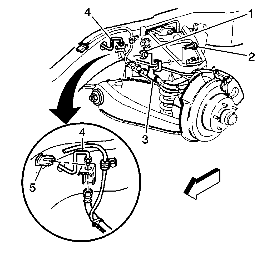
- Disconnect the steel pipe (4) from the top of the bracket.
- Remove the retainer (5).
- Remove the hose to speed sensor harness ties.
- Remove the support bracket (3).
- Remove the bolt.
- Remove the gaskets.
- Remove the hose.

Installation Procedure
- Install the hose (1) at the brake caliper, if applicable.
- Install the new brass gaskets (2).
- Install the bolt (3).
- Install the support bracket.
- Install the retainer (5).
- Connect the front brake steel pipe (4) to the hose.
- Join the brake hose to the speed sensor harness, if applicable. Use new ties.
- Bleed the brake system. Refer to Hydraulic Brake System Bleeding .

Important: Use new brass gaskets.
Notice: Use the correct fastener in the correct location. Replacement fasteners must be the correct part number for that application. Fasteners requiring replacement or fasteners requiring the use of thread locking compound or sealant are identified in the service procedure. Do not use paints, lubricants, or corrosion inhibitors on fasteners or fastener joint surfaces unless specified. These coatings affect fastener torque and joint clamping force and may damage the fastener. Use the correct tightening sequence and specifications when installing fasteners in order to avoid damage to parts and systems.
Tighten
Tighten the bolt to 44 N·m (32 lb ft).
Tighten
Tighten the support bracket nut to 18 N·m (13 lb ft).

Important: The hose must not be twisted. The hose must not contact any suspension components.
