Removal Procedure
Tools Required
| • | J 8107-2 Side Bearing Puller Plug |
| • | J 8614-01 Pinion Flange Holder |
| • | J 24385-C Differential Housing Spreader |
| • | J 29721 Differential Side Bearing Remover |
| • | J 29721-70 Side Bearing Adapters |
| • | J 39330 Bearing Race Remover |
| • | J 39331 Outer Bearing Race Remover |
| • | J 39704 Dial Indicator |
| • | J 39709 Universal Handle |
- Place the axle in a suitable support.
- Remove the bolts from the cover and the cover. This will drain the oil.
- Pull the axle shafts out of the axle housing to the point where the axle shafts are clear of the differential case.
- Remove the bearing cap bolts.
- Remove the bearing caps.
- Assemble the J 24385-C to the differential housing.
- Assemble the J 39704 .
- Preset the gage to a minimum of 5 mm (0.200 in). Rotate the indicator housing to zero on the dial.
- Spread the housing while examining the J 39704 .
- Remove the case from the housing using two pry bars.
- Remove the J 24385-C from the housing.
- Remove the bearing caps.
- Remove the bearings using the J 8107-2 J 29721 and J 29721-70
- Remove the shims.
- Check the outboard spacers for damage such as bends or deep groves caused by worn bearings. Replace any damaged spacers at the time of assembly.
- Place towels over the jaws of the vice. Place the differential case in the vice
- Remove the ring gear bolts. Discard the ring gear bolts.
- Remove the lock pin screw.
- Remove the pinion shaft using a hammer and brass drift.
- Rotate the side gears until the pinion gears are in the opening of the case. Remove the pinion gears and thrust washers.
- Remove the side gears and thrust washers.
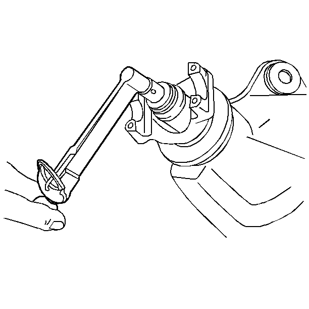
- Replace the cover using two bolts in order to keep the pinion from falling.
- Measure the drive pinion rotating torque. Record the measurement.
- Check for looseness of the pinion assembly by moving the assembly back and forth. Looseness indicates excessive bearing or pinion wear.
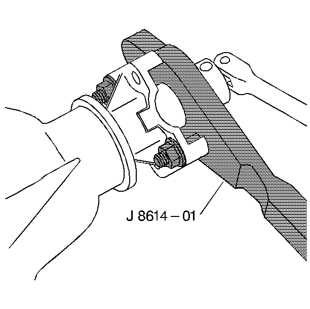
- Remove the pinion nut and washer using the J 8614-01 in order to hold the pinion.
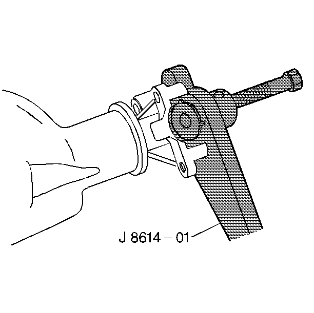
- Remove the pinion flange using the J 8614-01 .
- Use a soft-faced hammer to tap the pinion in order to remove the pinion from the pinion bore.
- Remove the cover and the pinion from the vehicle.
- Remove the pinion preload shims.
- Remove the pinion seal.
- Remove the outer bearing and oil slinger.
- Remove the pinion outer bearing cups from the axle using J 39330 .
- Remove the pinion outer adjusting shims and baffle, if used.
- Remove the pinion inner bearing cup using the J 39331 .
- Remove the pinion outer adjusting shims and baffle, if used.
- Remove the pinion inner bearing using the J 29721 and the J 29721-70 .
Important: Corresponding letters are stamped on the bearing caps and axle housing. The bearing caps must be reassembled exactly as removed.
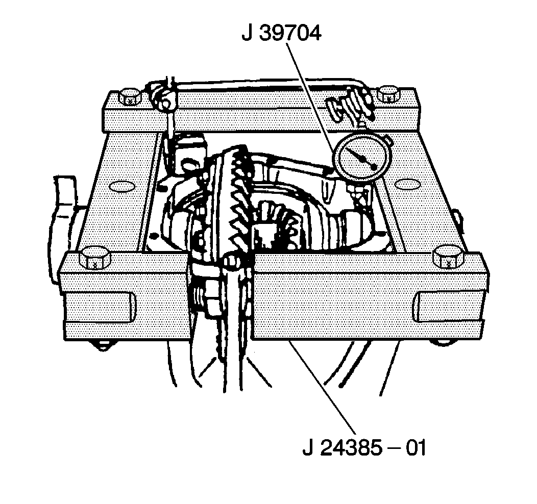
Notice: You may use the older style gage set if you already have them. The new style gages use the bearings as part of the gage system, while the older style uses a master block that acts as a master bearing.
Notice: Do not spread the axle housing more than 0.38 mm (0.015 inch). Overspreading the housing may result in component damage.

Important: Mark the bearing cups left and right and place each bearing cup with the corresponding proper bearing cap.
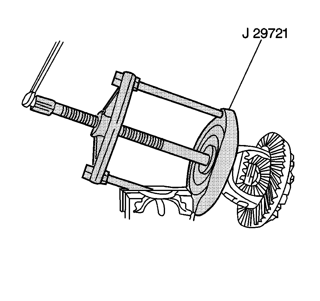
Important: Mark the bearings left and right and place each bearings with the corresponding set of bearing cap and cup.
Important: Mark the shims left or right.
Important: Replace the ring gear bolts with new ones at the time of assembly.
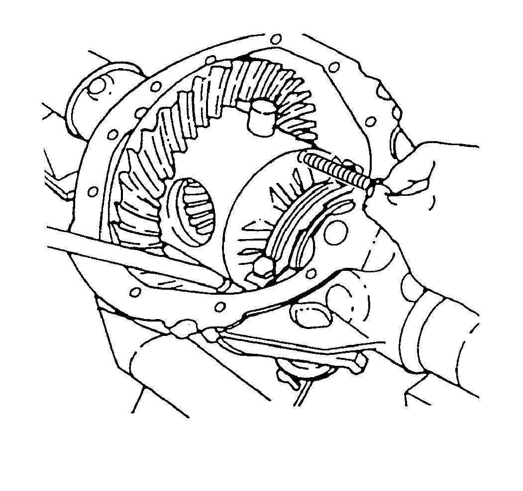
Notice: Do not pry the ring gear from the case. This will damage the ring gear and differential case.
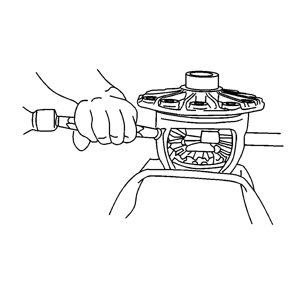
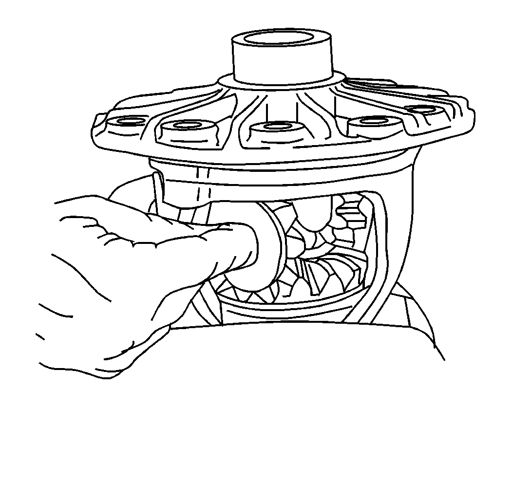
Important: Mark the side gears and thrust washers left and right
Important: Keep the shims together
Important: Keep the shims together.
Important: Keep the shims together

