Removal Procedure
- If the actuator will not hold pressure, move the column shift lever to the PARK position and apply the manual parking brake.
- Position a drain pan to catch the fluid that leaks out. Do not reuse the old fluid.
- Remove the access panel on the inboard side of the component box.
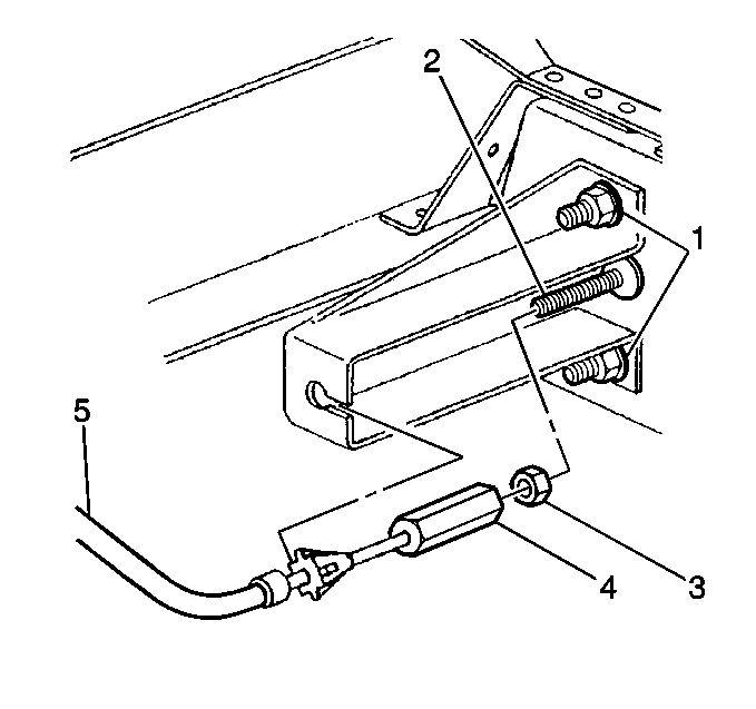
- Remove the parking brake cable (5).
- Remove the cable fitting (4) and the jam nut (3) from the actuator piston rod (2).
- Remove the hydraulic hose and the light switch.
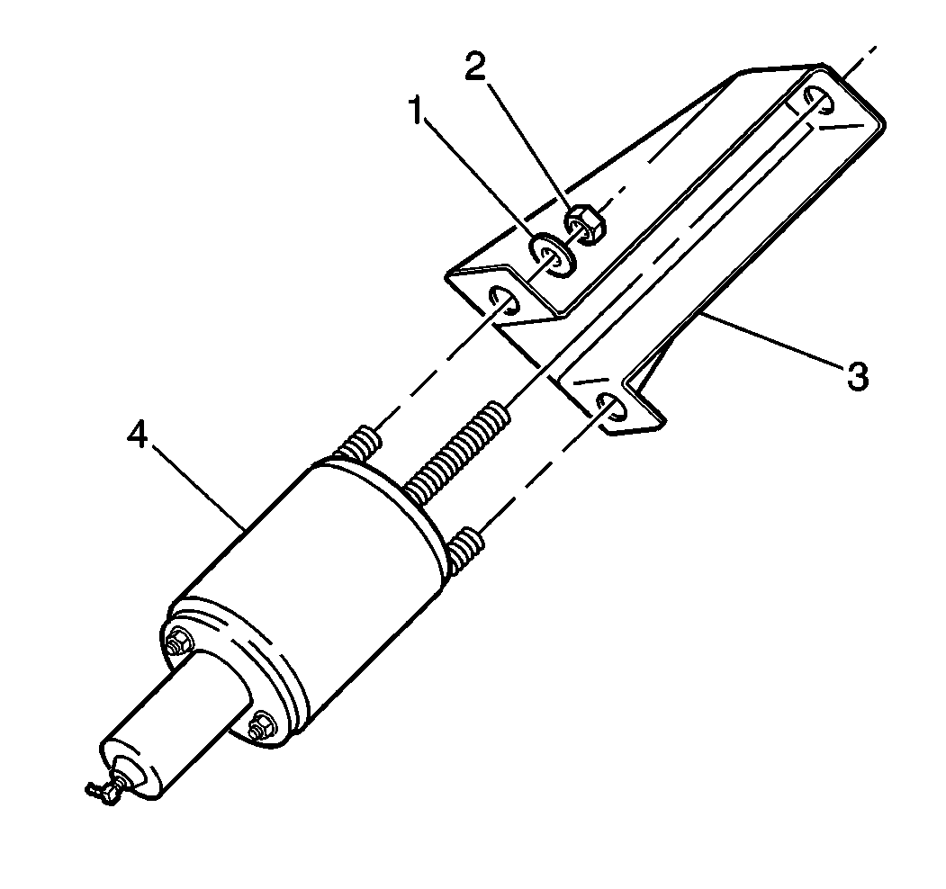
- Remove the actuator mounting nuts (2) and the washers (1).
- Remove the actuator (4).
CAUTION:: Do not disassemble the actuator. Always service the actuator as a unit. The actuator contains a large spring under tension. Disassembling the actuator allows the spring to expand with great force, which can result in personal injury.
CAUTION:: If the actuator will not hold pressure, do not unthread the parking brake cable from the actuator piston. The cable is under tension and unthreading the cable will cause the cable to spring and can result in personal injury.
Notice: When replacing any hydraulic components, the hydraulic system should be flushed with Dexron® III transmission fluid. This is to ensure that the hydraulic system is free of contaminants such as metal particles that may have been circulated through the system as a result of a component failure.
If the actuator will hold pressure, move the column shift lever to the NEUTRAL position with the ignition on. Apply the manual parking brake.

| • | If the actuator does not hold pressure, cut the parking brake cable with a bolt cutter. |
| • | If the actuator holds pressure, disconnect the cable at the relay lever and move the shift lever to the park position. |

Installation Procedure
- Install the actuator (4).
- Install the actuator mounting nuts (2) and the washers (1).
- Install the hydraulic hose and the light switch.
- Install the parking brake cable (5). Refer to Park Brake Cable Replacement .
- Install the access panel on the inboard side of the component box.
- Cycle the system at least 6 times. (Turn the ignition switch on and move the shift lever from PARK to NEUTRAL.) Inspect the fluid level. Refer to Checking and Adding Park Brake Fluid .
- Inspect the hydraulic system for leaks.
- Release the manual parking brake. Refer to Park Brake Cable Service/Adjustment .

Notice: Use the correct fastener in the correct location. Replacement fasteners must be the correct part number for that application. Fasteners requiring replacement or fasteners requiring the use of thread locking compound or sealant are identified in the service procedure. Do not use paints, lubricants, or corrosion inhibitors on fasteners or fastener joint surfaces unless specified. These coatings affect fastener torque and joint clamping force and may damage the fastener. Use the correct tightening sequence and specifications when installing fasteners in order to avoid damage to parts and systems.
Tighten
Tighten the nuts to 108 N·m (80 lb ft).
Tighten
Tighten the hydraulic pipe fitting to 16 N·m (12 lb ft).

Tighten
Tighten the fasteners to 12 N·m (106 lb in).
