Turn Signal Cancel Cam and Upper Bearing Inner Race - Assemble - Off Vehicle Column Shift
Tools Required
| • | J 41352 Modular
Column Holding Fixture |

- Align the block tooth
on the steering shaft assembly to the 12 o'clock position.

- Install the upper bearing
spring (3) onto the steering shaft assembly.
- Lubricate the turn signal cancel cam assembly (2) with
lithium grease.
- Install the turn signal cancel cam assembly (2) onto the
steering shaft assembly.
- Install the shaft lock cam (1) onto the steering shaft
assembly.

- Compress the shaft lock
cam using J 23653-91
and J 23653-SIR
.
- Install the new bearing retainer (1) into the groove on
the steering shaft assembly.
- Remove J 23653-91
and J 23653-SIR
.

- Install the lock bolt
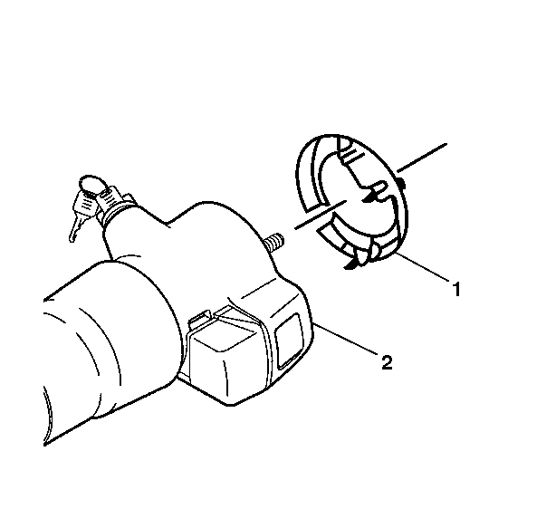
guard assembly (1) to the steering column (2).
- Remove the steering column and J 41352
from the vise.
Turn Signal Cancel Cam and Upper Bearing Inner Race - Assemble - Off Vehicle Floor Shift
Tools Required
| • | J 41352 Modular
Column Holding Fixture |

- Align the block tooth
on the steering shaft assembly to the 12 o'clock position.

- Install the upper bearing
spring (3) onto the steering shaft assembly.
- Lubricate the turn signal cancel cam assembly (2) with
lithium grease.
- Install the turn signal cancel cam assembly (2) onto the
steering shaft assembly.
- Install the shaft lock cam (1) onto the steering shaft
assembly.

- Compress the shaft lock
cam using J 23653-91
and J 23653-SIR
.
- Install the new bearing retainer (1) into the groove on
the steering shaft assembly.
- Remove J 23653-91
and J 23653-SIR
.

- Install the lock bolt
guard assembly (1) to the steering column (2).
- Remove the steering column and J 41352
from the vise.


