GM Service Manual Online
For 1990-2009 cars only
Makes
🢒
Chevrolet
🢒
1999
🢒
Chevy P32 RV/Van Chassis
🢒
Brakes
🢒
Antilock Brake System
🢒 Antilock Brake System Schematics
Antilock Brake System Schematics P32
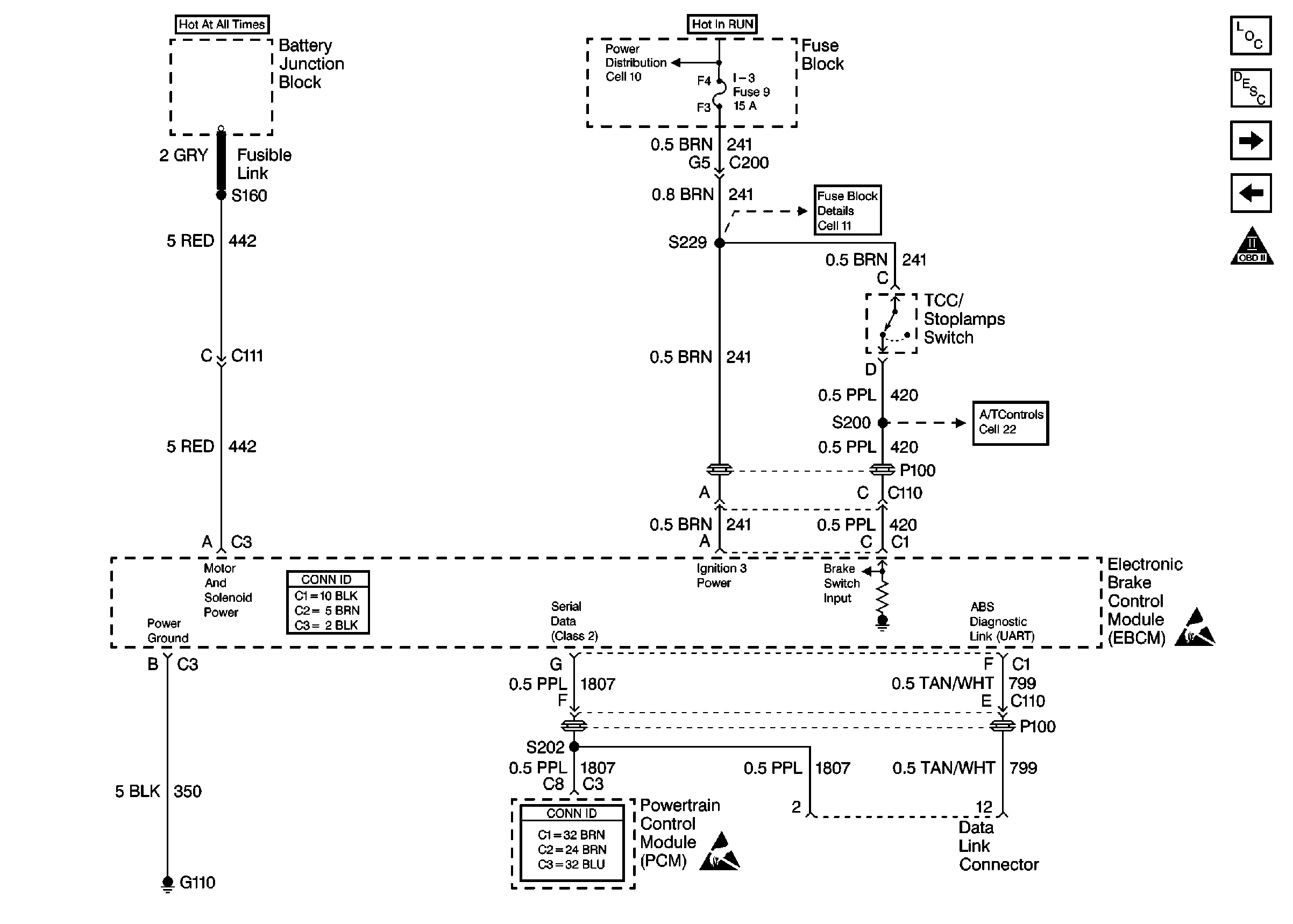
Figure
1:
Cell 44: Gas, ABS Power and Grounding, DLC Output
ABS Components P32
ABS Description
Cell 44: Diesel, ABS Power and Grounding, DLC Output
Cell 10: Battery, Starter and Junction Block
Cell 10: Ignition Switch and Fuse Block
Cell 11: I-3, TURN BU and HTR fuses, PWR CKT BRKR 2 and AUX CKT BRKR13
Cell 21: A/T Controls 1 - Stoplamp/TCC Switch, Internal Solenoids
Handling ESD Sensitive Parts Notice
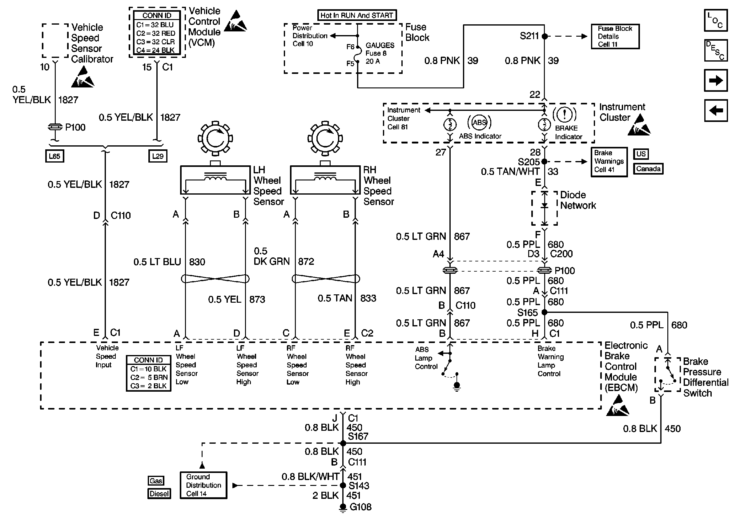
Figure
2:
Cell 44: Diesel, ABS Power and Grounding, DLC Output
ABS Components P32
ABS Description
Cell 44: US/Canada, ABS Inputs and Outputs
Cell 44: Gas, ABS Power and Grounding, DLC Output
Cell 10: Battery, Starter and Junction Block
Cell 10: Ignition Switch and Fuse Block
Cell 11: I-3, TURN BU and HTR fuses, PWR CKT BRKR 2 and AUX CKT BRKR13
Cell 22: A/T Controls 1 - Internal Solenoids, Brake Switches
Handling ESD Sensitive Parts Notice
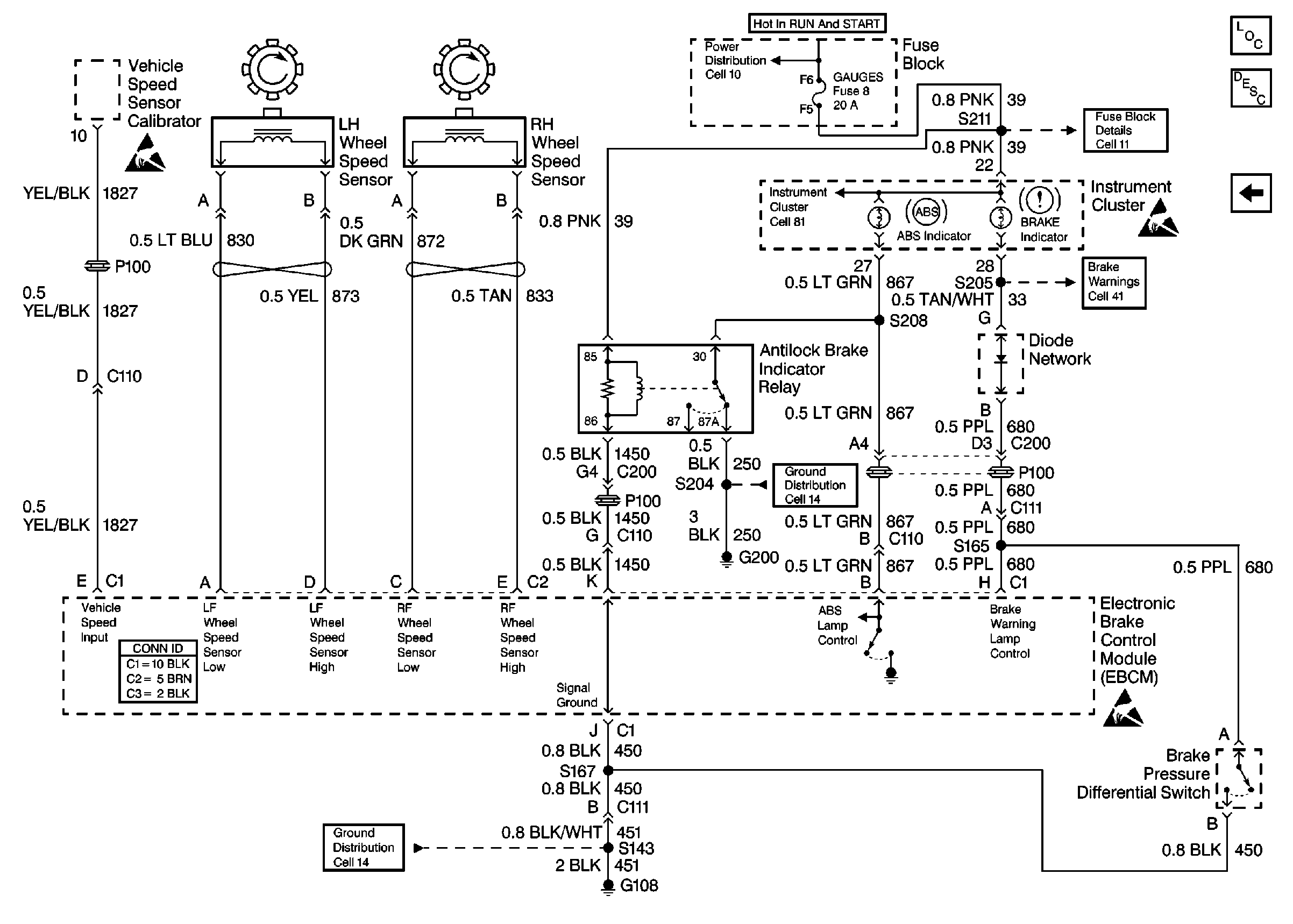
Figure
3:
Cell 44: US/Canada, ABS Inputs and Outputs
ABS Components P32
ABS Description
Cell 44: Export, ABS Inputs and Outputs
Cell 44: Diesel, ABS Power and Grounding, DLC Output
Handling ESD Sensitive Parts Notice
Cell 10: Ignition Switch and Fuse Block
Cell 81: Indicators
Cell 11: GAUGES and TRANS fuses
Handling ESD Sensitive Parts Notice
Cell 41: Brake Warning System - US
Cell 41: Brake Warning System - Canada
Handling ESD Sensitive Parts Notice
Cell 14: G108 [L29]
Cell 14: G108 [L65]
Figure
4:
Cell 44: Export, ABS Inputs and Outputs
ABS Components P32
ABS Description
Cell 44: US/Canada, ABS Inputs and Outputs
Handling ESD Sensitive Parts Notice
Cell 10: Ignition Switch and Fuse Block
Cell 81: Indicators
Cell 11: GAUGES and TRANS fuses
Handling ESD Sensitive Parts Notice
Cell 41: Brake Warning System - Export
Handling ESD Sensitive Parts Notice
Cell 14: G200
Cell 14: G108 [L65]
Antilock Brake System Schematics P42
Figure
1:
Cell 44: Gas, ABS Power and Grounding, DLC Output
ABS Components P42
ABS Description
Cell 44: Diesel, ABS Power and Grounding, DLC Output
Cell 10: Battery, Starter, and Junction Block
Cell 10: Ignition Switch and Fuse Block
Cell 11: I-3, TURN-B/U, and HTR fuses, AUX CKT BRKR 13
Cell 10: Ignition Switch and Fuse Block
Cell 11: Gauges fuse
Handling ESD Sensitive Parts Notice
Cell 81: Indicators
Cell 20: A/T Controls 1 - TCC, Solenoids
Cell 21: A/T Controls - Solenoids and TCC Stoplamp Switch
Cell 138: P42 BTSI Circuit
Handling ESD Sensitive Parts Notice
Figure
2:
Cell 44: Diesel, ABS Power and Grounding, DLC Output
ABS Components P42
ABS Description
Cell 44: ABS Inputs and Outputs
Cell 44: Gas, ABS Power and Grounding, DLC Output
Cell 10: Battery, Starter, and Junction Block
Cell 10: Ignition Switch and Fuse Block
Cell 11: Gauges fuse
Handling ESD Sensitive Parts Notice
Cell 81: Indicators
Cell 23: A/T Controls 1 - Stoplamp/TCC Switch, Internal Solenoids
Cell 138: P42 BTSI Circuit
Cell 22:A/T Controls 3 - Internal Solenoids and Stoplamp Switch
Handling ESD Sensitive Parts Notice
Figure
3:
Cell 44: ABS Inputs and Outputs
ABS Components P42
ABS Description
Cell 44: Diesel, ABS Power and Grounding, DLC Output
Cell 10: Ignition Switch and Fuse Block
Cell 11: Gauges fuse
Handling ESD Sensitive Parts Notice
Cell 81: Indicators
Cell 41: Brake Warning System - US
Cell 41: Brake Warning System - Canada
Handling ESD Sensitive Parts Notice
Cell 14: G108 [L57]