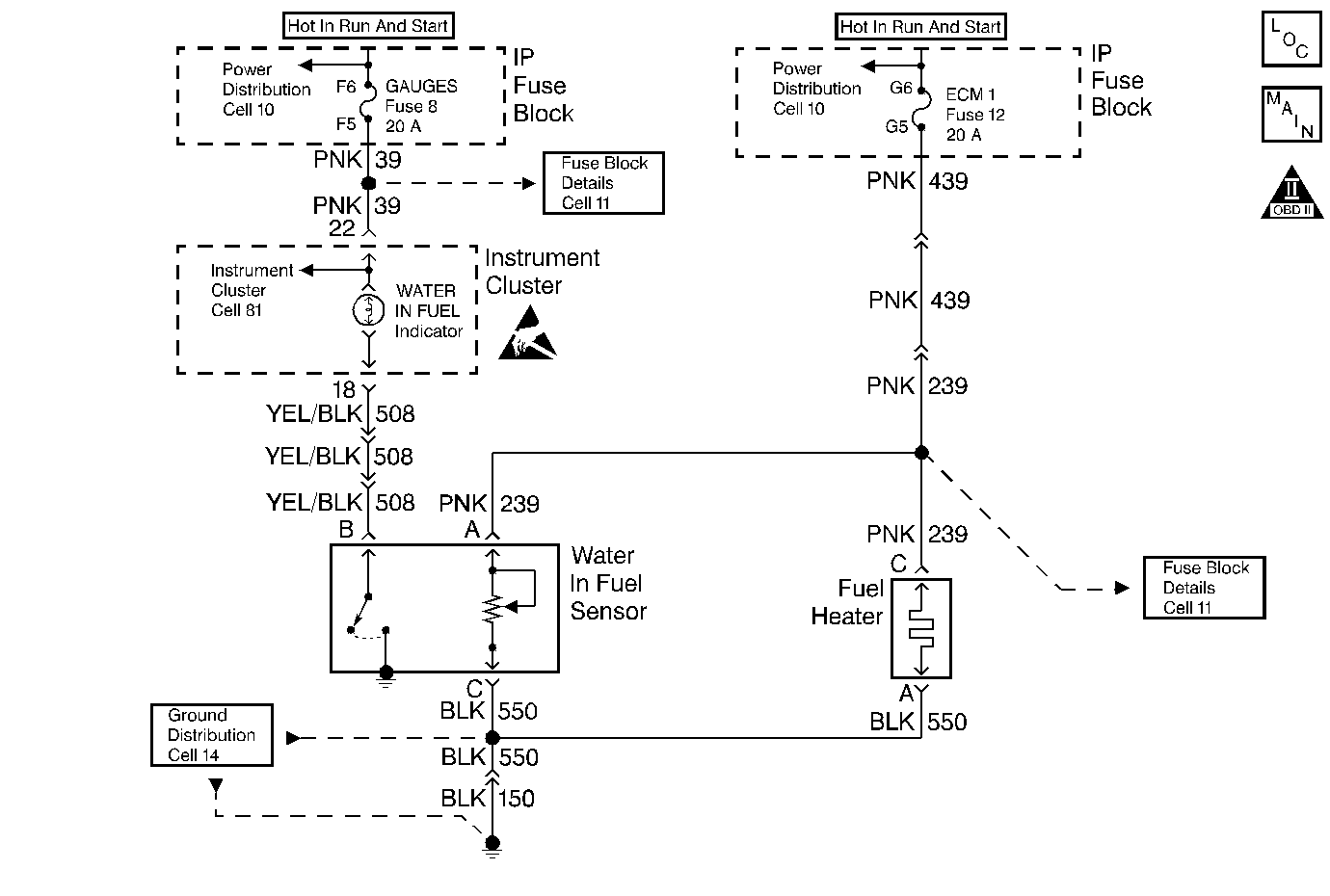
Water-in-Fuel Lamp Diagnosis EFI/MFI

Circuit Description
The fuel manager/filter assembly consists of the fuel heater, the water in fuel sensor and a filter. The filter contains the coalescer (the device that combines small droplets of water into larger ones) and the filter/separator.
A fuel lift pump delivers diesel fuel from the tank to the fuel filter. As fuel enters the filter, it passes first though the fuel heater. The heater contains a thermostatic switch. The switch opens or closes to turn the heater OFF or ON, depending on the temperature of the fuel.
The fuel then passes through the filter. Next the fuel flows through the water coalescer. Here the droplets of water in the fuel combine into larger drops, the drops fall to the water reservoir in the filter. When fuel flows from the fuel manager/filter assembly to the injection pump, the fuel is clean and free of water.
The solid state water in fuel sensor supplies voltage to a probe. When the probe touches water, the module closes a switch. This completes a circuit to ground to light the Water In Fuel lamp.
A time delay circuit in the water in fuel module grounds the lamp briefly to test the bulb each time the system is turned ON.
The fuel heater is operated by a built-in thermostatic switch. When the switch is closed, battery voltage is supplied to the heater.
Test Description
-
This step will determine if the ignition feed circuit is open.
-
This step will determine if the ground circuit is OK.
-
This step will determine if the fuse, bulb, and wiring are OK.
Step | Action | Value(s) | Yes | No |
|---|---|---|---|---|
1 | Turn the ignition ON leaving the engine OFF. Does the water In fuel light come ON briefly? | -- | ||
Is the test light ON? | -- | |||
With the test light, jumper the harness terminals A and C with the ignition still ON. Is the test light ON? | -- | |||
With the test light connected to ground, probe terminal B of the harness connector. Is the test light ON? | -- | |||
5 | Operate the vehicle within the conditions under which the concern was noted. Does the system operate properly? | -- | System OK | |
6 |
Was a problem found? | -- | ||
7 |
Was a problem found? | -- | ||
8 |
Was a problem found? | -- | ||
9 |
Was a problem found? | -- | ||
10 | Repair the open in the lamp circuit. Refer to Wiring Repairs. Is the action complete? | -- | -- | |
11 | Replace the water In fuel sensor. Refer to Water in Fuel Indicator Sensor Replacement . Is the action complete? | -- | -- | |
12 | Operate the vehicle within the conditions under which the original problem was noted. Does the system operate properly? | -- | System OK |
