Brake Pedal Replacement Motorhome
Removal Procedure
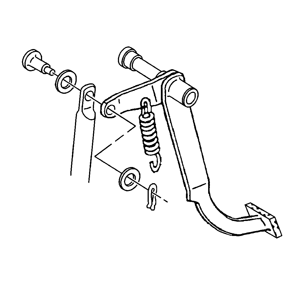
- Remove the retainer.
- Remove the washer.
- Remove the pin and washer.
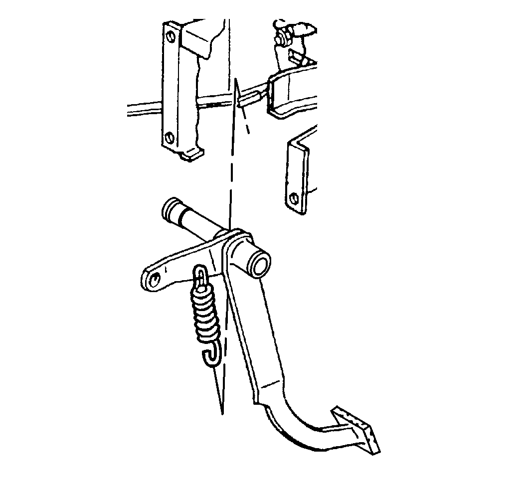
- Remove the brake rod.
- Remove the return spring.
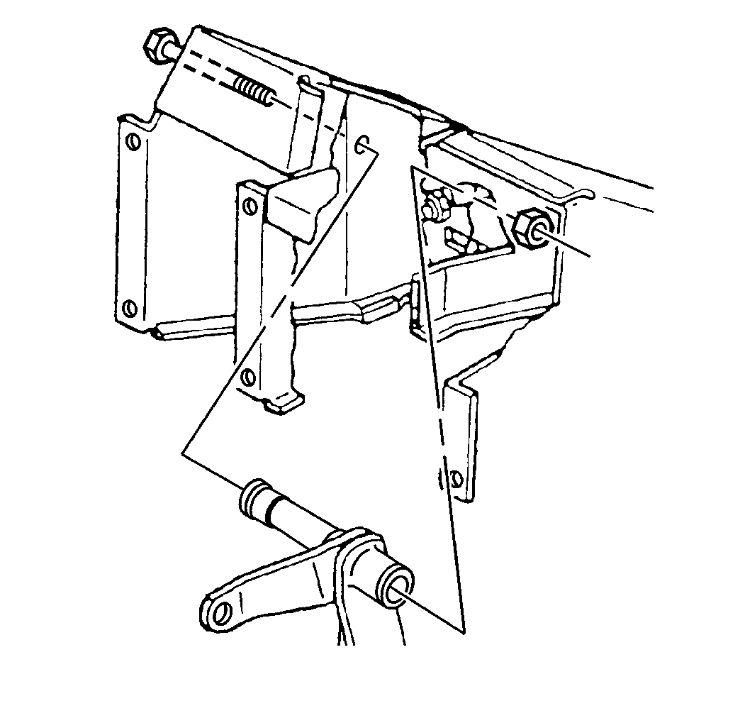
- Remove the nut and bolt.
- Remove the brake pedal.
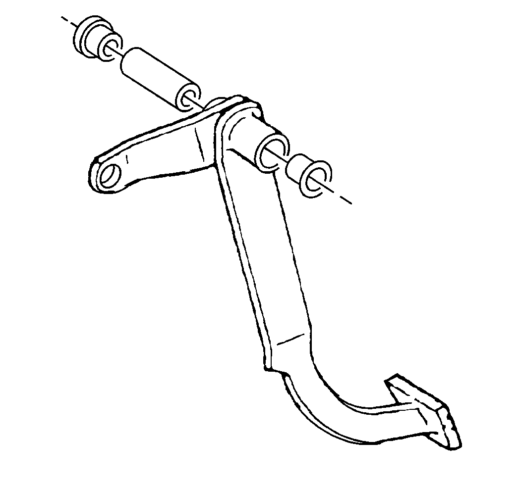
- Remove the bushings.
- Remove the spacer.
Installation Procedure
- Install the spacer.
- Install the bushings.
- Install the brake pedal.
- Install the bolt and nut.
- Install the return spring.
- Install the washer and pin.
- Install the brake rod.
- Install the washer and the retainer.
- Check the Stoplamp Switch Adjustment. Refer to Stop Lamp Switch Adjustment .

Notice: Use the correct fastener in the correct location. Replacement fasteners must be the correct part number for that application. Fasteners requiring replacement or fasteners requiring the use of thread locking compound or sealant are identified in the service procedure. Do not use paints, lubricants, or corrosion inhibitors on fasteners or fastener joint surfaces unless specified. These coatings affect fastener torque and joint clamping force and may damage the fastener. Use the correct tightening sequence and specifications when installing fasteners in order to avoid damage to parts and systems.

Tighten
Tighten the nut to 10 N·m (89 lb in).


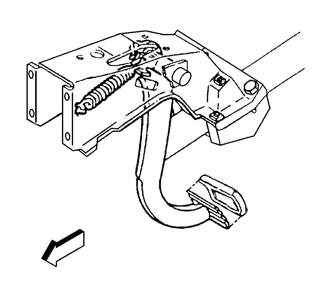
Brake Pedal Replacement Commercial
Removal Procedure
- Remove the pin.
- Remove the nut.
- Remove the bolt.
- Remove the pushrod.
- Remove the clutch attaching components, if equipped.
- Remove the clutch pedal, if equipped.
- Remove the return spring.
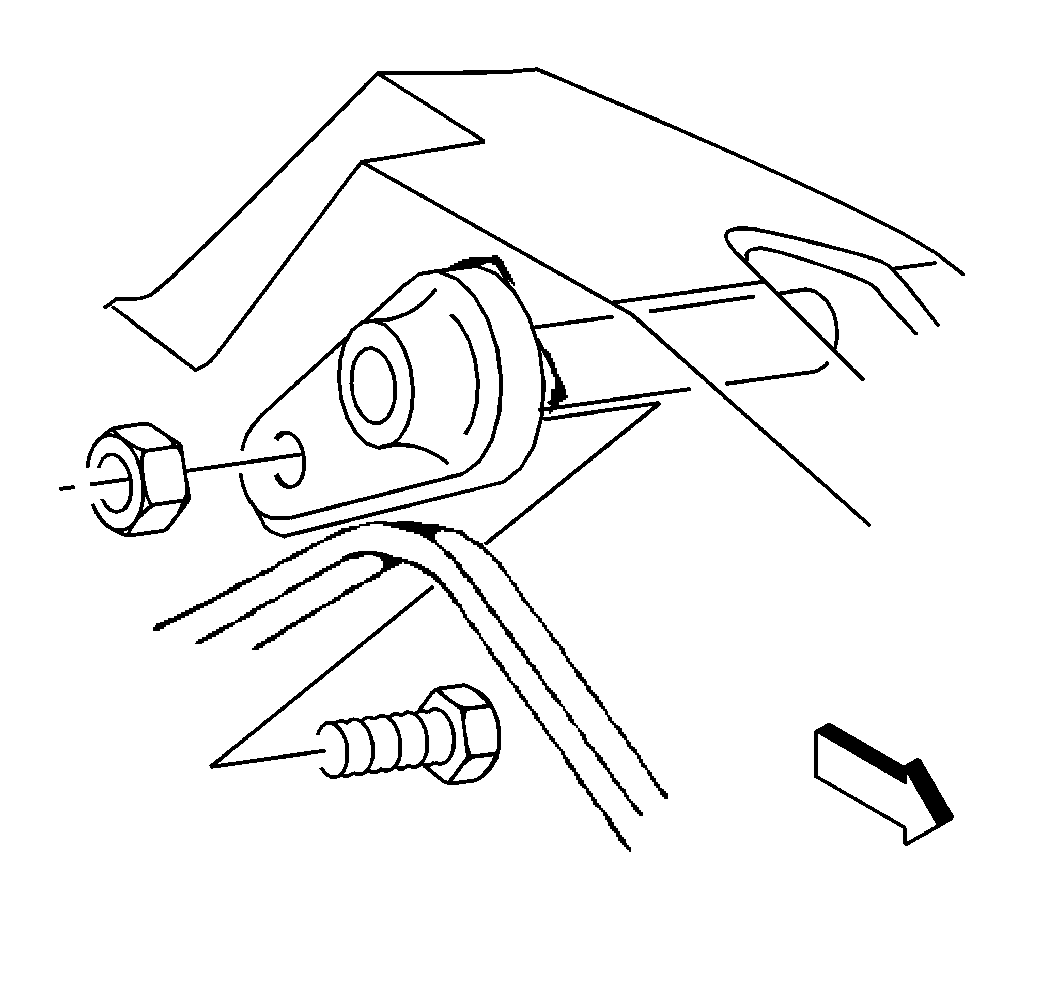
- Remove the nut and bolt.
- Remove the shaft.
- Remove the brake pedal.
- Remove the bushings.
Installation Procedure
- Lubricate the pivot points with Lubriplate GM P/N 1050109, or equivalent.
- Install the bushings.
- Install the brake pedal.
- Install the shaft.
- Install the bolt and nut.
- Install the clutch pedal, if equipped.
- Install the return spring.
- Install the clutch attaching components, if equipped.
- Install the pushrod.
- Install the bolt.
- Install the nut.
- Install a new pin.
- Check the stoplamp switch adjustment. Refer to Stop Lamp Switch Adjustment .


Notice: Use the correct fastener in the correct location. Replacement fasteners must be the correct part number for that application. Fasteners requiring replacement or fasteners requiring the use of thread locking compound or sealant are identified in the service procedure. Do not use paints, lubricants, or corrosion inhibitors on fasteners or fastener joint surfaces unless specified. These coatings affect fastener torque and joint clamping force and may damage the fastener. Use the correct tightening sequence and specifications when installing fasteners in order to avoid damage to parts and systems.
Tighten
Tighten the nut to 10 N·m (89 lb in).

Brake Pedal Replacement Commercial Linkage
Removal Procedure
- Disconnect the rod from the brake pedal.
- Remove the bolt and nut.
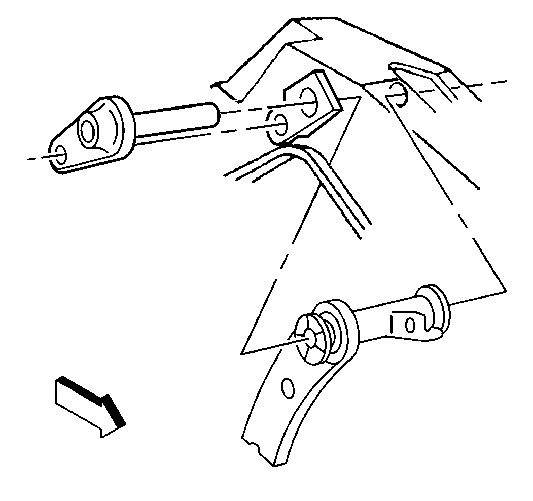
- Remove the lever assembly. The rod will pull out of the booster.
- Remove the bushings and spacer.
- Remove the bolt, nut, and washer.
- Remove the retainer.
- Remove the retainers.
- Remove the washers.
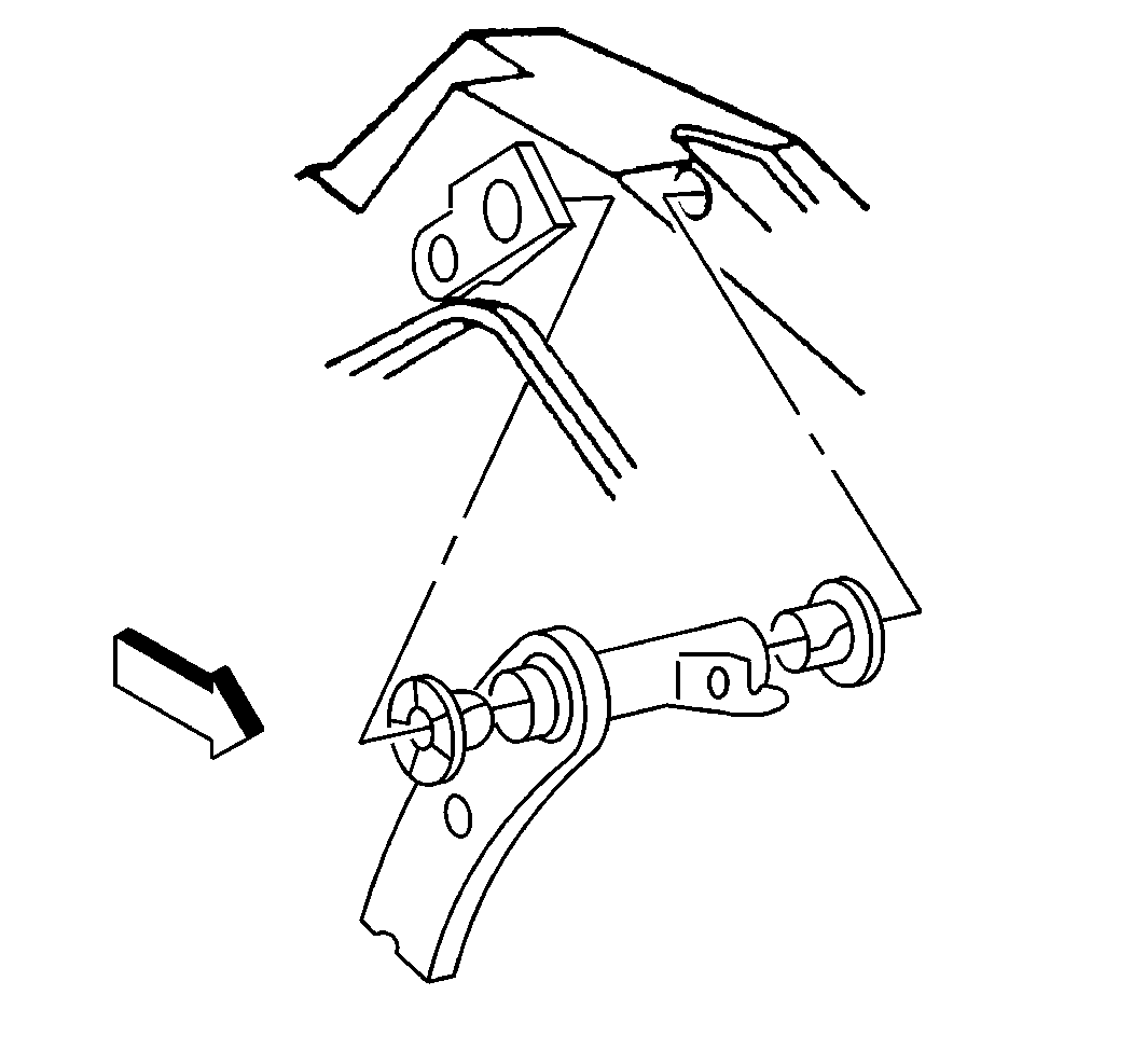
- Remove the brake pedal rod and the booster rod.
- Remove the wave washers.
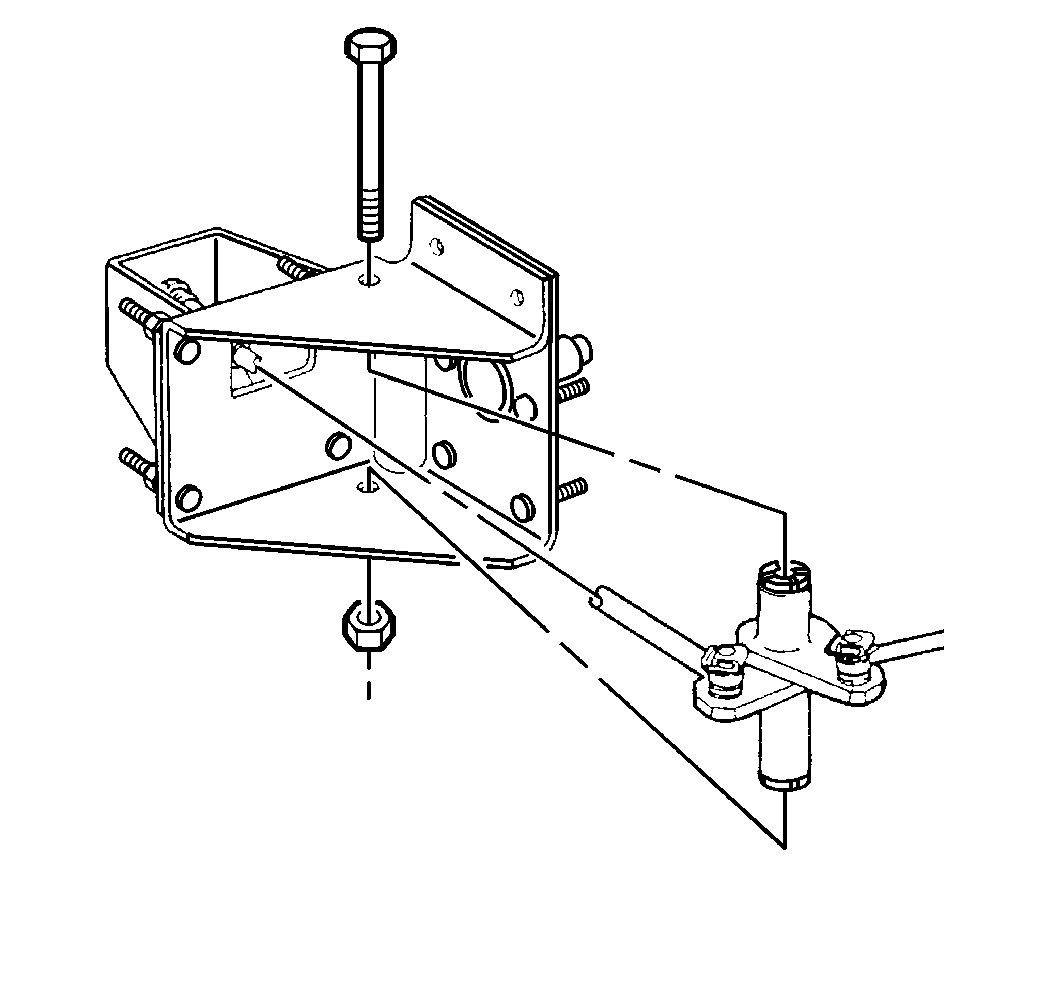
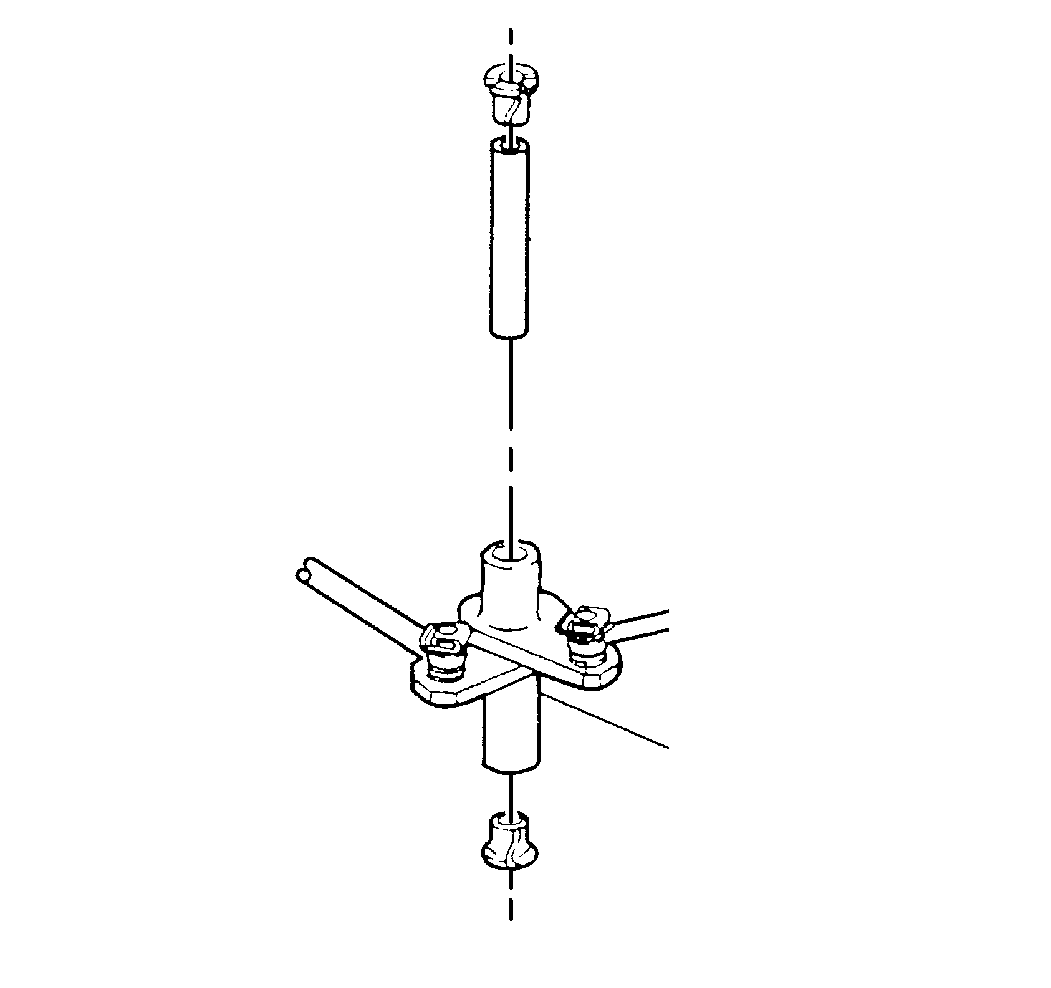
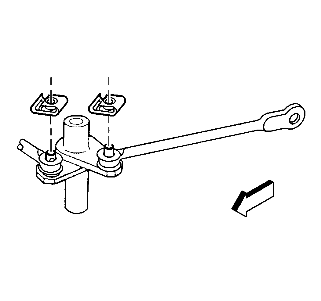
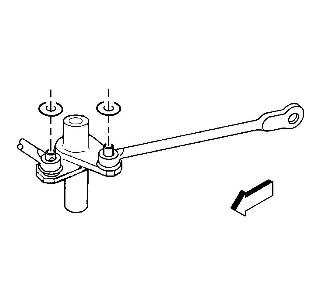
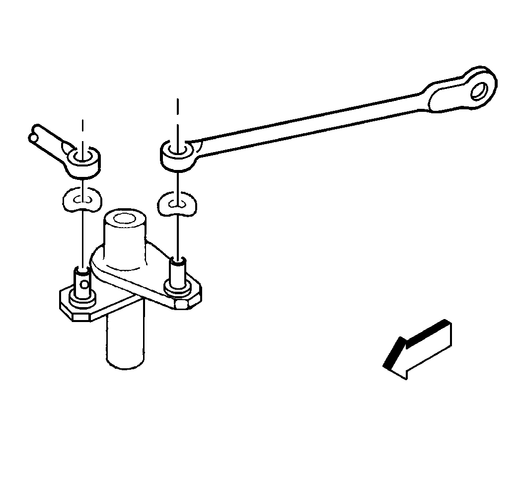
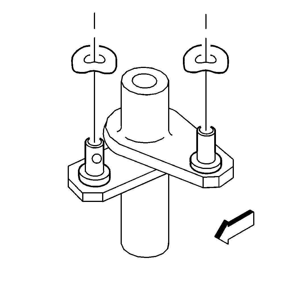
Installation Procedure
- Lubricate the pivot points with Lubriplate GM P/N 1050109 or equivalent.
- Install the wave washers.
- Install the brake pedal rod and the booster rod to the lever.
- Install the washers.
- Install the retainers.
- Install the retainer.
- Install the bolt washer and nut.
- Install the spacer.
- Install the bushings.
- Install the lever assembly. Insert the rod into the booster. Push the rod until it seats.
- Install the bolt and nut.
- Connect the rod to the brake pedal.


Notice: Use the correct fastener in the correct location. Replacement fasteners must be the correct part number for that application. Fasteners requiring replacement or fasteners requiring the use of thread locking compound or sealant are identified in the service procedure. Do not use paints, lubricants, or corrosion inhibitors on fasteners or fastener joint surfaces unless specified. These coatings affect fastener torque and joint clamping force and may damage the fastener. Use the correct tightening sequence and specifications when installing fasteners in order to avoid damage to parts and systems.
Tighten
Tighten the nut to 34 N·m (25 lb ft).


Tighten
Tighten the nut to 55 N·m (41 lb ft).
Brake Pedal Replacement Motorhome Linkage
Removal Procedure
- Remove the retainer.
- Remove the nut.
- Remove the bolt and washers.
- Remove 4 screws.
- Raise the vehicle and support the vehicle with safety stands.
- Remove the retainer.
- Remove the nut.
- Remove the washer.
- Remove the brake rod.
- Remove the boot.
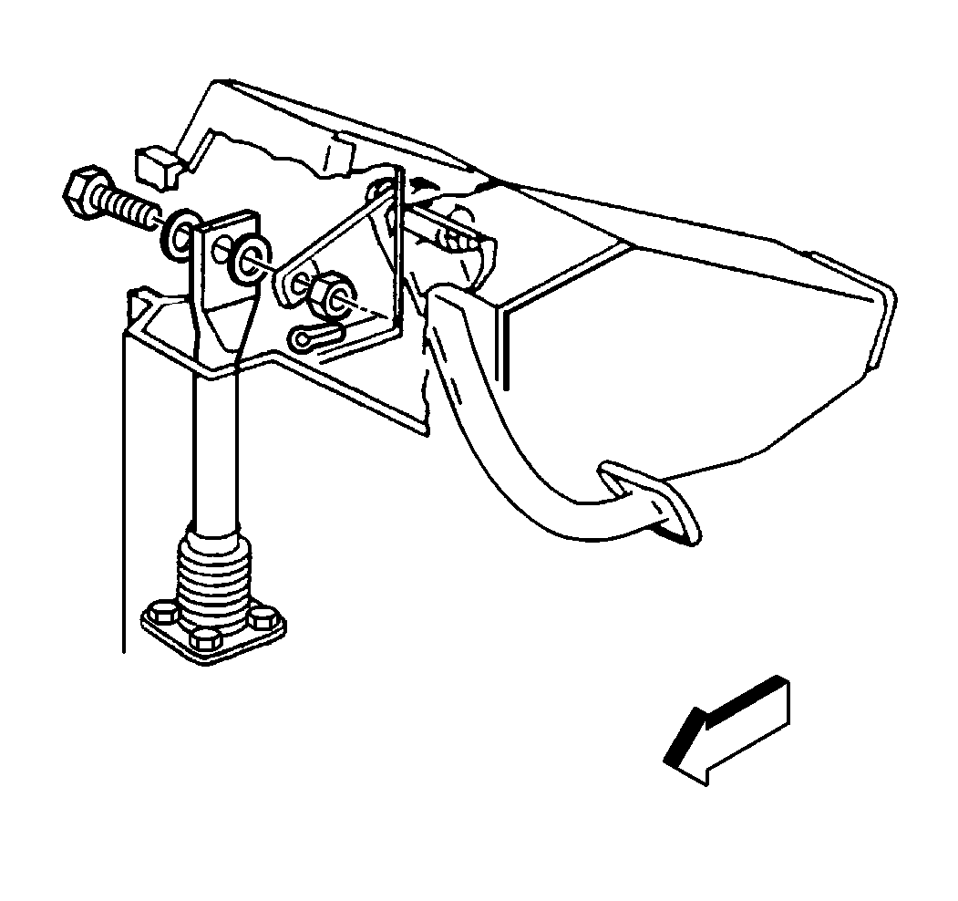
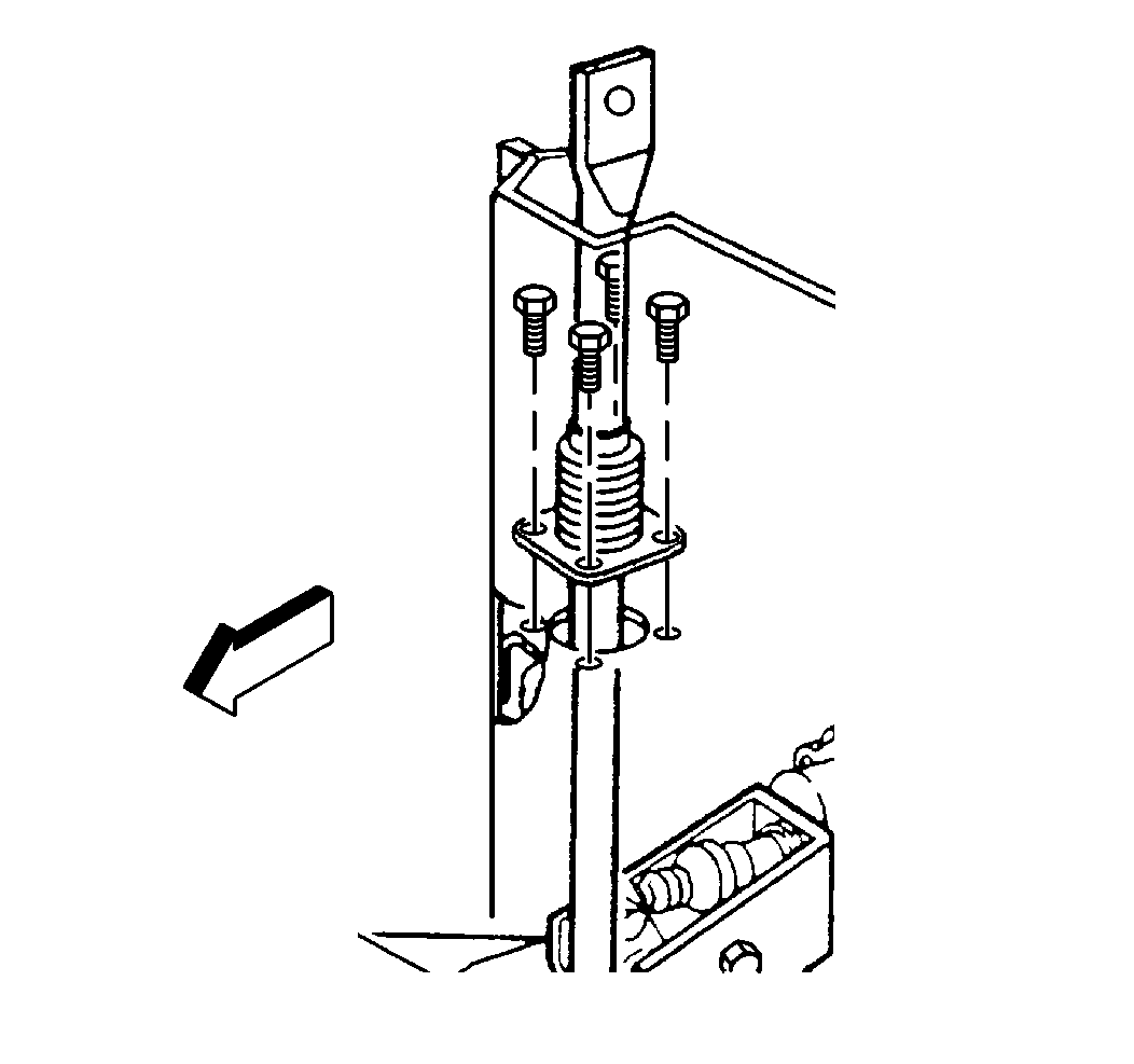
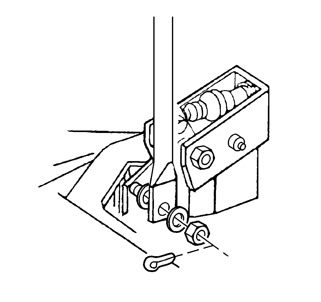
Installation Procedure
- Lubricate the pivot points with Lubriplate GM P/N 1050109 or equivalent.
- Install the boot.
- Install the brake rod.
- Install the washer.
- Install the nut.
- Install the retainer.
- Lower the vehicle.
- Install 4 boot screws.
- Install the bolt and washers.
- Install the nut.
- Install the retainer.

Notice: Use the correct fastener in the correct location. Replacement fasteners must be the correct part number for that application. Fasteners requiring replacement or fasteners requiring the use of thread locking compound or sealant are identified in the service procedure. Do not use paints, lubricants, or corrosion inhibitors on fasteners or fastener joint surfaces unless specified. These coatings affect fastener torque and joint clamping force and may damage the fastener. Use the correct tightening sequence and specifications when installing fasteners in order to avoid damage to parts and systems.
Tighten
Tighten the nut to 34 N·m (25 lb ft).

Tighten
Tighten the screws to 1.7 N·m (15 lb in).

Tighten
Tighten the nut to 34 N·m (25 lb ft).
