Parking Brake Cable Replacement Front Pedal Type
Removal Procedure
- Raise the vehicle and support the vehicle with safety stands. Refer to Lifting and Jacking the Vehicle in General Information.
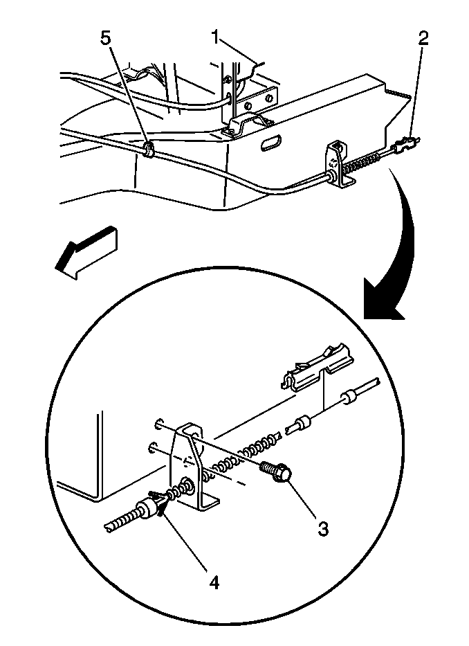
- Disconnect the nut from the equalizer.
- Remove the connector (2).
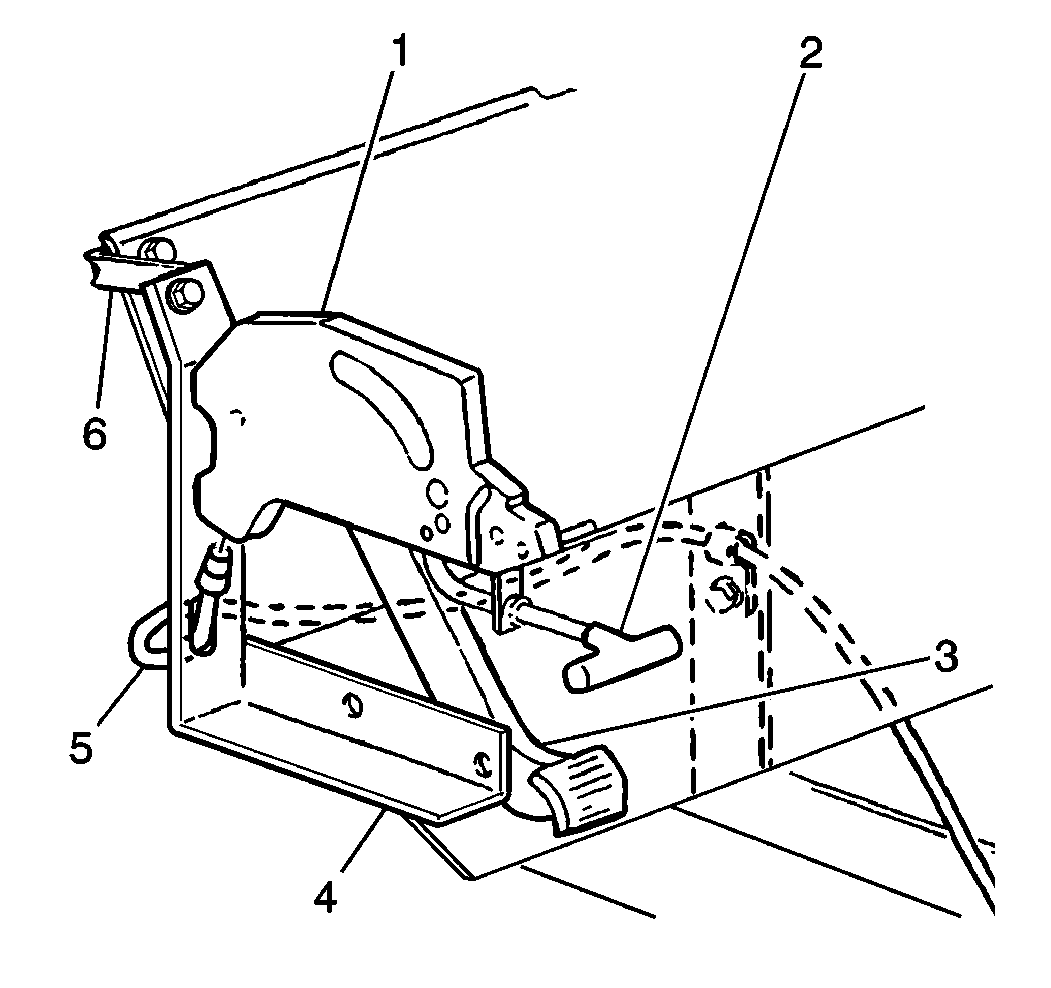
- Disconnect the cable from the frame bracket. Bend the retaining fingers (4).
- Disconnect the cable from the pedal assembly (1).
- Remove the retainer clip bolts and the retainer clips (5).
- Remove the cable assembly (5). Attach a piece of wire to the cable to help in the installation.
Installation Procedure
- Install the cable assembly (5). Ensure the retaining fingers are completely through the holes. Bend the retainers back into place.
- Install the retainer clips (5) and the retainer clip bolts.
- Connect the cable (5) to the pedal assembly.
- Connect the cable to the frame bracket.
- Install the connector (2).
- Connect the nut to the equalizer.
- Adjust the parking brake. Refer to Park Brake Cable Service/Adjustment .
- Lower the vehicle.


Notice: Use the correct fastener in the correct location. Replacement fasteners must be the correct part number for that application. Fasteners requiring replacement or fasteners requiring the use of thread locking compound or sealant are identified in the service procedure. Do not use paints, lubricants, or corrosion inhibitors on fasteners or fastener joint surfaces unless specified. These coatings affect fastener torque and joint clamping force and may damage the fastener. Use the correct tightening sequence and specifications when installing fasteners in order to avoid damage to parts and systems.
Tighten
Tighten the retainer clip bolts to 17 N·m (13 lb ft).
Parking Brake Cable Replacement Center
Removal Procedure
- Raise the vehicle and support the vehicle with safety stands. Refer to Lifting and Jacking the Vehicle in General Information.
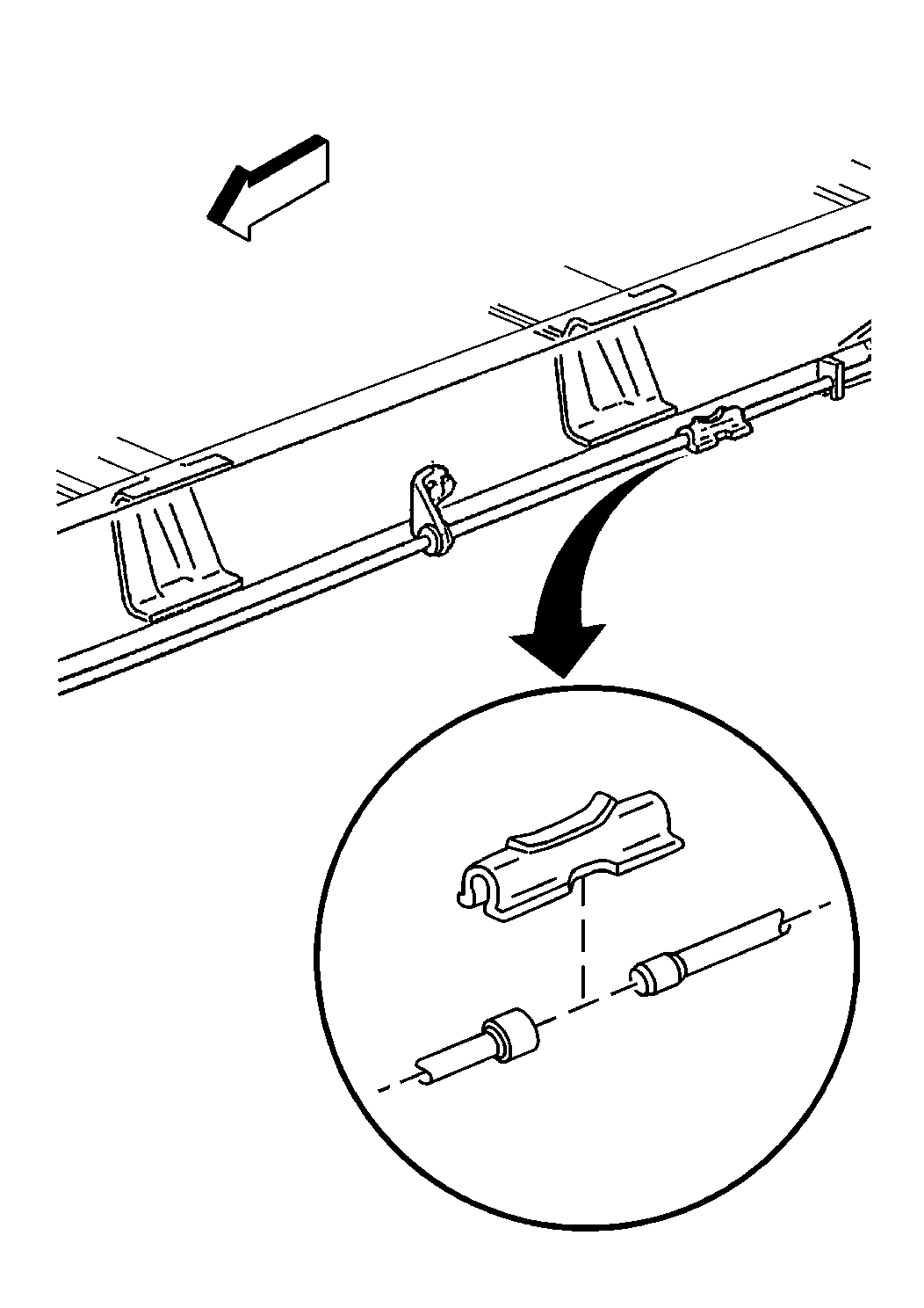
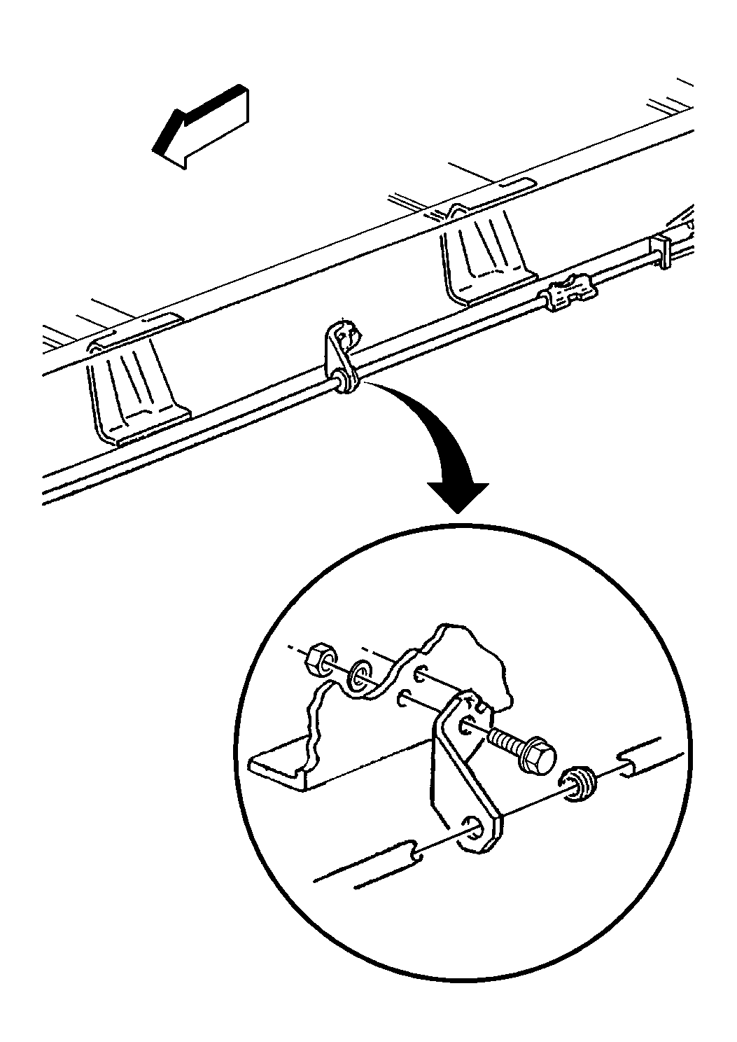
- Remove the nut from the equalizer.
- Remove the front and rear connectors.
- Remove the cable through the guide grommets.
Installation Procedure
- Install the cable through the guide grommets.
- Install the connectors.
- Install the nut to the equalizer.
- Adjust the parking brake. Refer to Park Brake Cable Service/Adjustment .
- Lower the vehicle.

Parking Brake Cable Replacement Actuator
Removal Procedure
Important: If the actuator will hold pressure, place the vehicle in neutral and turn the ignition to the ON position. This will release the load on the cable. Disconnect the cable at the relay lever. Shift the vehicle into park and turn the ignition to the OFF position. Proceed with the procedures below.
- If the actuator will not hold pressure, move the column shift lever to the park position. If the actuator will hold pressure, move the column shift lever to the neutral position and turn the ignition switch ON.
- Raise the vehicle and support the vehicle with safety stands. Refer to Lifting and Jacking the Vehicle in General Information.
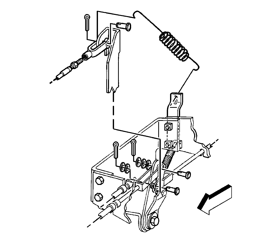
- Remove the cotter pin and the washers.
- Remove the clevis pin and remove cable from relay lever.
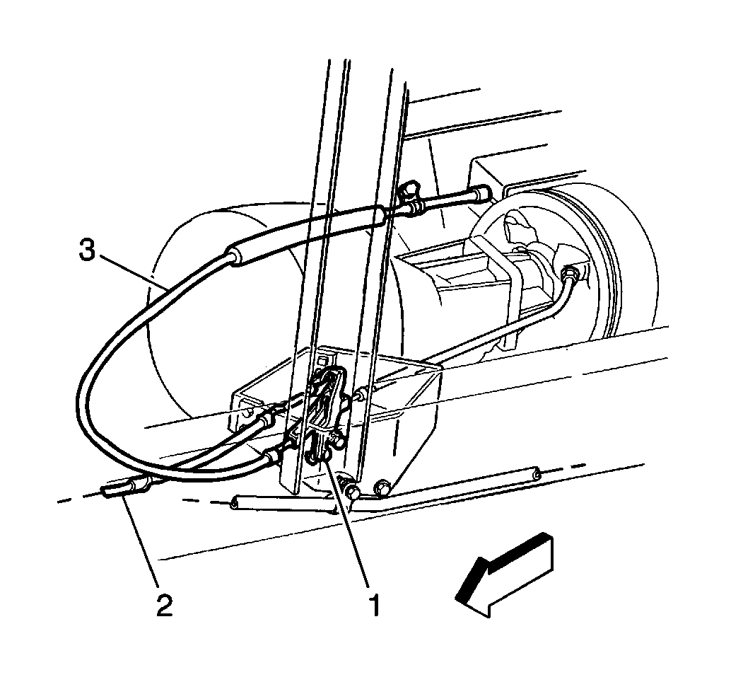
- Remove the cable from the relay lever (1) and bracket if the actuator holds pressure. Otherwise, cut the parking brake cable with a bolt cutter.
- Remove the bolt which secures a cable clip to the frame.
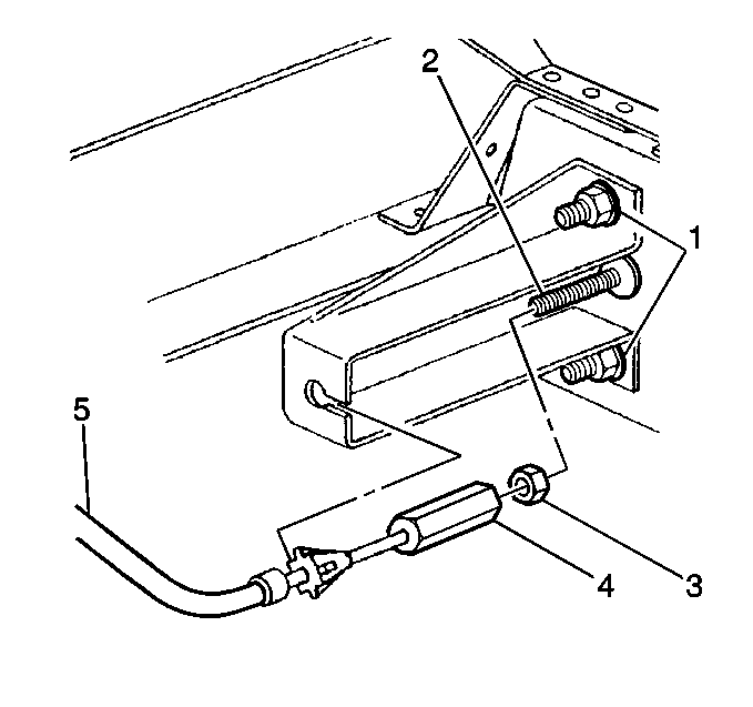
- Disconnect the parking brake cable (5) by removing the cable fitting (4) and the jamb nut (3) from the actuator rod (2).
CAUTION:: If the actuator will not hold pressure, do not unthread the parking brake cable from the actuator piston. The cable is under tension and unthreading the cable will cause the cable to spring and can result in personal injury.
Installation Procedure
- Connect the actuator cable (3) to the relay lever.
- Install the clevis pin, the washers and the cotter pin.
- Install the frame clip bolt to secure the cable and install the straps to secure the cable.
- Connect the cable (5) to the actuator bracket.
- Connect the cable fitting (4) and the jamb nut (3) to the actuator piston rod (2).
- Install the jamb nut against the cable fitting to obtain between 30-37 mm (1.20-1.44 in) travel.
- Adjust the parking brake. Refer to Park Brake Cable Service/Adjustment .
- Lower the vehicle. Refer to Lifting and Jacking the Vehicle in General Information.


Notice: Use the correct fastener in the correct location. Replacement fasteners must be the correct part number for that application. Fasteners requiring replacement or fasteners requiring the use of thread locking compound or sealant are identified in the service procedure. Do not use paints, lubricants, or corrosion inhibitors on fasteners or fastener joint surfaces unless specified. These coatings affect fastener torque and joint clamping force and may damage the fastener. Use the correct tightening sequence and specifications when installing fasteners in order to avoid damage to parts and systems.
Tighten
Tighten the frame clip bolt to 8 N·m (71 lb in).

Tighten
Tighten the jamb nut to 45 N·m (33 lb ft).
Parking Brake Cable Replacement Front Lever Type
Removal Procedure
- Raise the vehicle and support the vehicle with safety stands. Refer to Lifting and Jacking the Vehicle in General Information.
- Remove the nut from the equalizer.
- Remove the connector.
- Remove the retainer clip bolts and retainer clips.
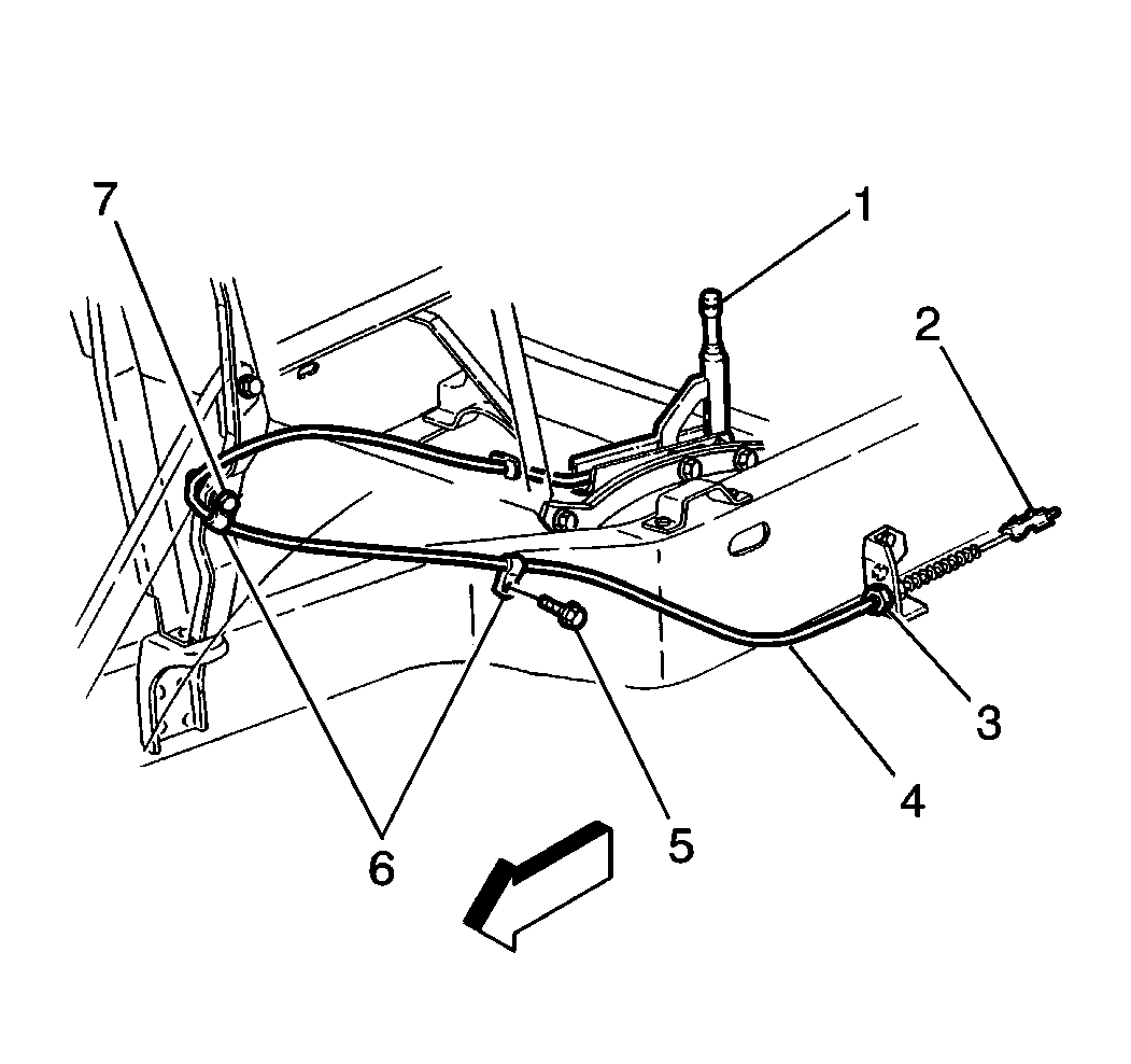
- Disconnect the cable from the lever assembly (1).
- Remove the retaining fingers (3).
- Remove the cable assembly (4). Attach a piece of wire to the cable to help in the installation.

Installation Procedure
- Install the cable assembly (4).
- Install the retaining fingers (3).
- Connect the cable to the lever assembly (1).
- Install the retainer clips and the retainer clip bolts.
- Install the connector.
- Install the nut to the equalizer.
- Adjust the parking brake. Refer to Park Brake Cable Service/Adjustment .
- Lower the vehicle.

Notice: Use the correct fastener in the correct location. Replacement fasteners must be the correct part number for that application. Fasteners requiring replacement or fasteners requiring the use of thread locking compound or sealant are identified in the service procedure. Do not use paints, lubricants, or corrosion inhibitors on fasteners or fastener joint surfaces unless specified. These coatings affect fastener torque and joint clamping force and may damage the fastener. Use the correct tightening sequence and specifications when installing fasteners in order to avoid damage to parts and systems.
Tighten
Tighten the retainer clip bolts to 17 N·m (13 lb ft).

Parking Brake Cable Replacement Rear
Removal Procedure
- Raise the vehicle and support the vehicle with safety stands. Refer to Lifting and Jacking the Vehicle in General Information.
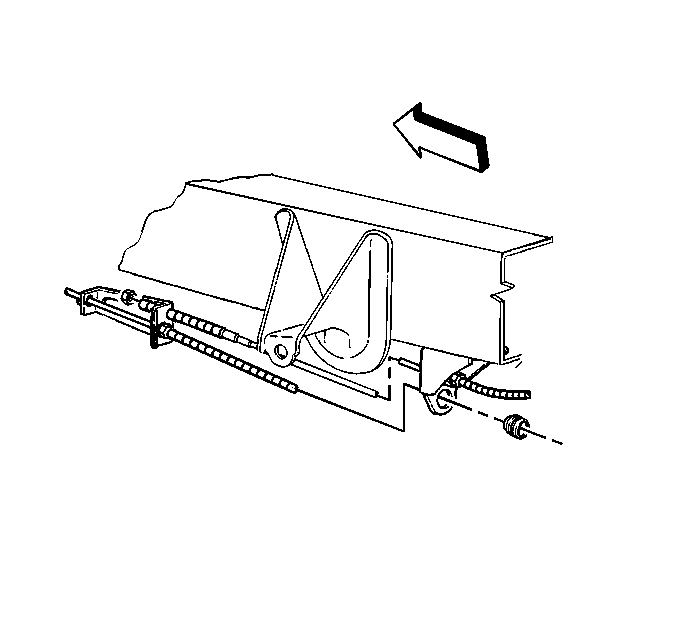
- Mark the position of RH rear cable nut at the equalizer and remove the nut.
- Remove the connector.
- Disconnect the LH cable from the equalizer and frame bracket, and the RH cable from the frame bracket.
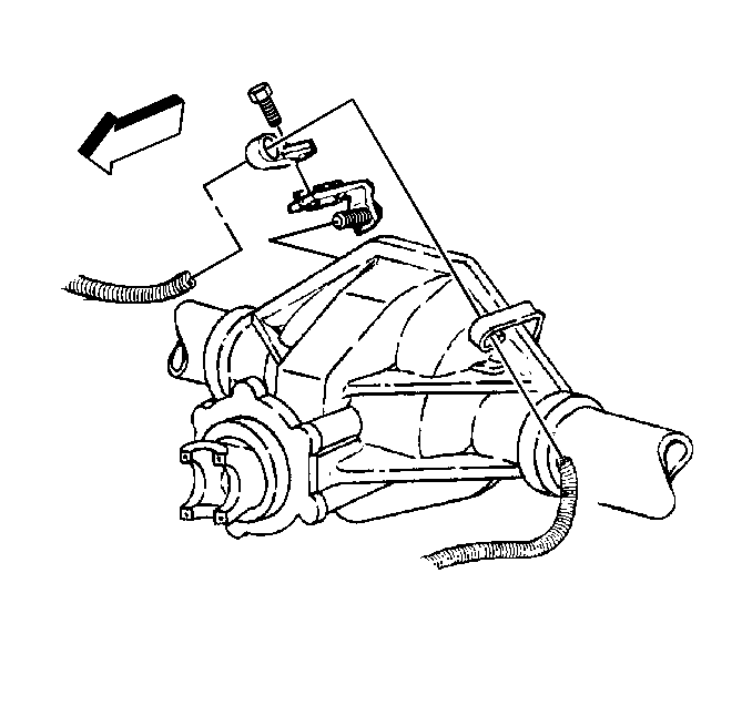
- Disconnect the RH cable from the axle brackets.
- Remove the RH and LH rear brake hub and drum assemblies and disconnect the parking brake cable from each brake side. Refer to Brake Drum Replacement in Drum Brakes.
- Remove the retaining clips.
- Remove the cable assemblies.


Installation Procedure
- Install the cable assemblies to each brake side. Make sure all of the retaining fingers are completely through the backing plate.
- Install the retaining clips.
- Install the hub and drum assembly on each side. Refer to Brake Drum Replacement in Drum Brakes.
- Rout the RH rear cable through the clip on the rear axle bracket and tighten the bolt to secure the clip to the bracket.
- Rout and secure the RH and LH cables through the side member bracket and the equalizer.
- Install the connector.
- Install the RH cable nut at the equalizer to the previously marked position.
- Check the parking brake adjustment. Refer to Park Brake Cable Service/Adjustment .
- Lower the vehicle.

Notice: Use the correct fastener in the correct location. Replacement fasteners must be the correct part number for that application. Fasteners requiring replacement or fasteners requiring the use of thread locking compound or sealant are identified in the service procedure. Do not use paints, lubricants, or corrosion inhibitors on fasteners or fastener joint surfaces unless specified. These coatings affect fastener torque and joint clamping force and may damage the fastener. Use the correct tightening sequence and specifications when installing fasteners in order to avoid damage to parts and systems.
Tighten
Tighten the bolt to 31 N·m (23 lb ft).


