Product Safety - Fuel Module Reservoir Assembly

| Subject: | 05027A -- FUEL MODULE RESERVOIR ASSEMBLY |
| Models: | 2000-2001 CHEVROLET 1500 SERIES SUBURBAN |
| 2000-2001 GMC 1500 SERIES YUKON XL |
THE SERVICE PROCEDURE IN THIS BULLETIN HAS BEEN REVISED TO INCLUDE THE USE OF TOOL J 41413-300, EVAP CAP/PLUG KIT. PLEASE REVIEW THE SERVICE PROCEDURE IMMEDIATELY. DISCARD ALL COPIES OF BULLETIN 05027 ISSUED OCTOBER 2005.
Condition
General Motors has decided that a defect, which relates to motor vehicle safety, exists in certain 2000-2001 Chevrolet 1500 Series Suburban and GMC 1500 Series Yukon XL vehicles. Some of these vehicles were built with fuel module reservoir assemblies that contain fuel pump wires and/or connectors that may overheat under certain operating conditions. Fuel pump wires that overheat may become exposed and result in one or more of the following conditions: 1) if the ignition circuit wire is exposed and shorts to ground, the fuel pump fuse will blow, disabling the fuel pump and causing an engine stall or no-start condition; 2) if the ignition circuit or ground wire is exposed and shorts to the fuel level sender card wires, inaccurate fuel level readings may result; 3) if sufficient heat is conducted to the pass-through connector, a hole in the connector may result, which may cause a Service Engine Soon light to be illuminated during the emission system diagnostics routine. Fuel vapor, and in some cases liquid fuel, may leak out of the fuel tank through the hole in the connector body. If a sufficient amount of fuel were to leak out and if an ignition source were present, a vehicle fire could occur.
Correction
Dealers are to remove the fuel tank, remove the fuel module reservoir assembly, and install a new service kit. The service kit includes a new pass-through connector, wiring harness for the fuel pump and fuel sender card.
Vehicles Involved
Involved are certain 2000-2001 Chevrolet 1500 Series Suburban and GMC 1500 Series Yukon XL vehicles built within these VIN breakpoints:
Year | Division | Model | From | Through |
|---|---|---|---|---|
2000 | Chevrolet | Suburban | YG100002 | YG229688 |
YJ100001 | YJ211728 | |||
2001 | Chevrolet | Suburban | 1G100015 | 1G289620 |
1J100003 | 1J318221 | |||
2000 | GMC | Yukon XL | YG100003 | YG229685 |
YJ100017 | YJ211810 | |||
2001 | GMC | Yukon XL | 1G100013 | 1G289614 |
1J100013 | 1J318207 |
Important: Dealers should confirm vehicle eligibility through GMVIS (GM Vehicle Inquiry System) prior to beginning recall repairs. [Not all vehicles within the above breakpoints may be involved.]
For US and Canada
For dealers with involved vehicles, a Campaign Initiation Detail Report containing the complete Vehicle Identification Number, customer name and address data has been prepared and will be loaded to the GM DealerWorld (US) Recall Information, GMinfoNet (Canada) Recall Reports. Dealers will not have a report available if they have no involved vehicles currently assigned.
For Export
For dealers with involved vehicles, a Campaign Initiation Detail Report containing the complete Vehicle Identification Number, customer name and address data has been prepared, and is being furnished to involved dealers. Dealers will not receive a report with the recall bulletin if they have no involved vehicles currently assigned.
The Campaign Initiation Detail Report may contain customer names and addresses obtained from Motor Vehicle Registration Records. The use of such motor vehicle registration data for any purpose other than follow-up necessary to complete this recall is a violation of law in several states/provinces/countries. Accordingly, you are urged to limit the use of this report to the follow-up necessary to complete this recall.
Parts Information
Parts required to complete this recall are to be obtained from General Motors Service Parts Operations (GMSPO). Please refer to your "involved vehicles listing" before ordering parts. Normal orders should be placed on a DRO = Daily Replenishment Order. In an emergency situation, parts should be ordered on a CSO = Customer Special Order.
Part Number | Description | Qty |
|---|---|---|
15824379 | Harness Kit, F/Tnk F/Pmp Mdl Wrg | 1 |
Service Procedure
| • | J 44402 Fuel Tank Sending Unit Wrench |
| • | J 34730-1A Fuel Pressure Gauge |
| • | J 37088-A Quick Connect Tools |
| • | J 38125-8 Wire Stripper Crimper |
| • | J 41413-300 EVAP Cap/Plug Kit |
Removal and Rebuild Procedure
Caution: Before servicing any electrical component, the ignition key must be in the OFF or LOCK position and all electrical loads must be OFF, unless instructed otherwise in these procedures. If a tool or equipment could easily come in contact with a live exposed electrical terminal, also disconnect the negative battery cable. Failure to follow these precautions may cause personal injury and/or damage to the vehicle or its components.
- Disconnect the negative battery cable.
- Remove and discard the "ECM B" fuse.
- Loosen the fuel filler cap in order to relieve the fuel tank vapor pressure.
- Connect the J 34730-1A fuel pressure gauge to the fuel pressure valve. Wrap a shop towel around the fitting while connecting the gauge in order to avoid spillage.
- Install the bleed hose of the gauge into an approved container.
- Open the valve on the gauge to bleed the system pressure. The fuel connections are now safe for servicing.
- Drain any fuel remaining in the gauge into an approved container.
- Raise the vehicle. Refer to Lifting and Jacking the Vehicle in SI, Document #349918, if necessary.
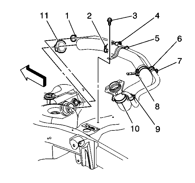
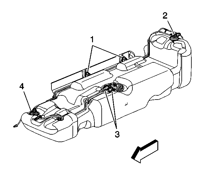
- Loosen the fuel fill hose clamp (2).
- Disconnect the fuel fill hose from the fuel fill pipe.
- Loosen the vent hose clamp (4).
- Disconnect the vent hose from the vent pipe.
- Use a hand or air operated pump device in order to drain as much fuel through the fuel fill pipe as possible.
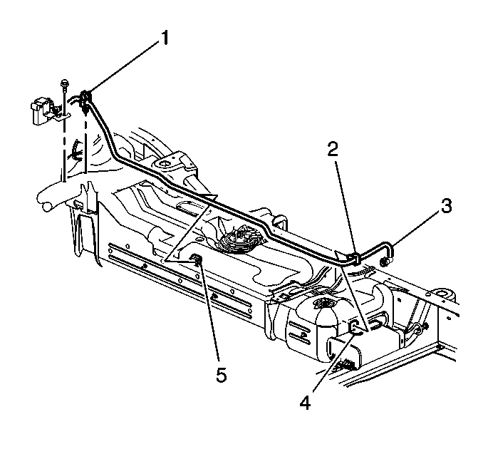
- Remove the left and right evaporative emission (EVAP) canister mount bolts.
- Disconnect the pipes (1) (2) at the EVAP canister.
- Disconnect the vent valve pipe (2) at the EVAP canister bracket.
- Remove the EVAP canister from the vehicle.
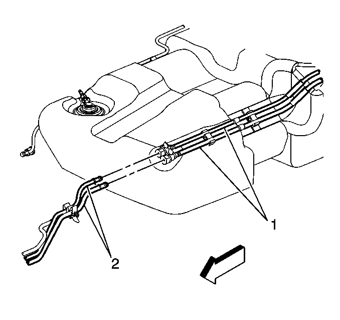
- Disconnect the chassis fuel pipes (2) at the fuel tank pipes (1). Refer to Quick Connect Fitting(s) Service (Plastic Collar) SI Document #546475, if necessary.
- Using J 41413-300, EVAP Cap/Plug Kit, cap the fuel and EVAP pipes in order to prevent possible fuel system contamination.
- Disconnect the EVAP vent pipe at the fuel tank clip.
- With the aid of an assistant, support the fuel tank.
- Remove the fuel tank strap attaching bolts.
- Remove the fuel tank straps.
- Carefully lower the rear of the fuel tank slightly.
- Remove the fuel sender cover on the Suburban only.
- Disconnect the fuel sender and the fuel pressure sensor electrical connectors.
- Remove the fuel tank.
- Place the fuel tank in a suitable work area.
- Remove the fuel feed and return pipes (3) from the fuel sender and the retaining clips.
- Remove the fuel sender assembly retaining ring using the J 44402 fuel tank sending unit wrench.
- Remove the fuel sender assembly and the seal. Discard the seal. In the extremely rare and unlikely event that the fuel sender assembly must be replaced, be sure that the new assembly contains the recall kit parts. Comparison of the electrical connector that goes through the cover with the electrical connector in the recall kit is the easiest part. If they are the same, the recall kit is not required.
- Clean the fuel sender sealing surfaces.
- Disconnect the fuel pump electrical connector (5).
- Remove the fuel level sensor electrical connector retaining clip (6).
- Disconnect the fuel level sensor electrical connector (7).
- Remove the fuel level sensor-retaining clip (4).
- Remove the purple fuel level sensor wiring from the wire retention cavities.
- Carefully depress the two retaining tabs on either side of the fuel pump reservoir.
- Separate the fuel pump module from the reservoir.
- Remove the fuel level sensor (3).
- Note the orientation of the electrical connector on the top of the sending unit cover.
- Unlatch the lock tab on the bottom of the electrical connector in the sending unit cover and push the electrical connector out the top of the cover.
- Remove and discard the old electrical connector O-ring from the top of the sending unit cover if it did not come out with the connector.
- Clean any dirt or debris from the electrical connector opening in the sending unit cover.
- Make sure the O-ring is properly seated on the new electrical connector and lubricate it with oil in the packet contained in the kit.
- Align the new electrical connector in the opening of the sending unit cover as noted earlier and install it with finger pressure. Make sure it snaps into place.
- Make sure the new electrical connector is completely seated and the lock tab is in place.
- Note the orientation of the float arm assembly on the fuel level sensor.
- Place a small flat screwdriver under the float arm assembly near the brass colored insert.
- Gently twist the screwdriver to remove the float arm assembly.
- Install the float arm assembly onto the new fuel level sensor in the orientation noted above and align with snaps. Use finger pressure to snap the float arm assembly into the new fuel level sensor.
- Make sure the float arm assembly is completely seated under the retainers on the fuel level sensor.
- Install the fuel level sensor (3) to the reservoir. Make sure it snaps into place and is fully seated.
- Install the fuel level sensor-retaining clip (4). Make sure it snaps into place and is fully seated.
- Assemble the fuel pump module into the reservoir. Be sure the fuel pump module is completely seated and the two retaining tabs snap into place and are properly engaged into the reservoir.
- Connect the fuel level sensor electrical connector (7). Make sure it snaps into place and is fully seated.
- Install the fuel level sensor electrical connector retaining clip (6). Make sure it snaps into place and is fully seated.
- Route the purple fuel level sensor wires into the wire retention cavities.
- Connect the fuel pump electrical connector (5). Make sure it snaps into place and is fully seated.
Caution: Remove the fuel tank cap and relieve the fuel system pressure before servicing the fuel system in order to reduce the risk of personal injury. After you relieve the fuel system pressure, a small amount of fuel may be released when servicing the fuel lines, the fuel injection pump, or the connections. In order to reduce the risk of personal injury, cover the fuel system components with a shop towel before disconnection. This will catch any fuel that may leak out. Place the towel in an approved container when the disconnection is complete.
Caution: Gasoline or gasoline vapors are highly flammable. A fire could occur if an ignition source is present. Never drain or store gasoline or diesel fuel in an open container, due to the possibility of fire or explosion. Have a dry chemical (Class B) fire extinguisher nearby.

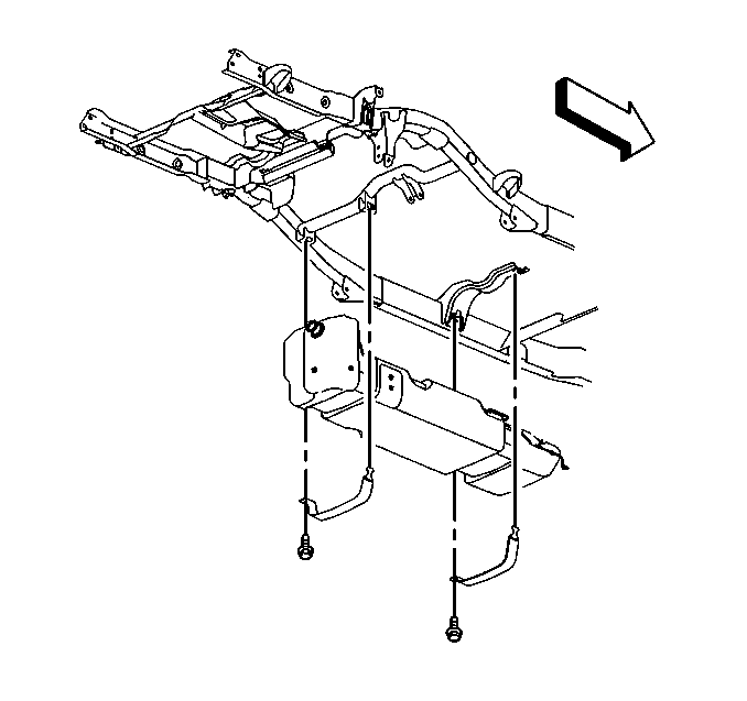
Notice: Do not bend the fuel tank straps. Bending the fuel tank straps may damage the straps.
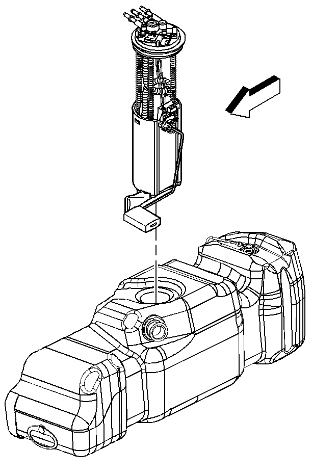
Notice: Do not handle the fuel sender assembly by the fuel pipes. The amount of leverage generated by handling the fuel pipes could damage the joints.
Caution: Drain the fuel from the fuel sender assembly into an approved container in order to reduce the risk of fire and personal injury. Never store the fuel in an open container.

Caution: The O-ring may be damaged during installation if it is not properly lubricated.
Caution: Check the fuel level sensor float arm to be certain it is not binding and moves freely. A binding float arm may cause inaccurate fuel gauge readings.
Installation Procedure
Caution: In order to reduce the risk of fire and personal injury that may result from a fuel leak, always replace the fuel sender gasket when reinstalling the fuel sender assembly.
- Install the new seal on the fuel tank.
- Install the fuel sender assembly into the fuel tank.
- Install the fuel sender assembly retaining ring using the J 44402 fuel tank sending unit wrench.
- Connect the fuel feed and return pipes to the fuel sender and the retaining clips.
- Replace the original chassis connector:
- With the aid of an assistant, support and partially raise the fuel tank front end first.
- Connect the fuel sender and the fuel pressure sensor electrical connectors.
- Install the fuel sender cover on the Suburban only.
- Fully raise the fuel tank.
- Install the fuel tank straps.
- Install the fuel tank strap attaching bolts.
- Connect the fuel fill hose and the vent hose to the pipes.
- Connect the EVAP vent pipe to the fuel tank clip.
- Remove the caps from the fuel and EVAP pipes.
- Connect the chassis fuel pipes at the fuel tank pipes.
- Install the EVAP canister to the vehicle.
- Connect the vent valve pipe to the EVAP canister bracket.
- Connect the pipes to the EVAP canister.
- Install the left and right EVAP canister mounting bolts.
- Lower the vehicle.
- Refill the fuel tank.
- Install the fuel filler cap.
- Install the new fuel pump fuse, contained in the kit, into the vehicle's electrical center (ECM B).
- Connect the negative battery cable.
- Inspect for leaks.
Important: The fuel pump strainer must be in a horizontal position when the fuel sender is installed in the tank. When installing the fuel sender assembly, assure that the fuel pump strainer does not block full travel of the float arm.
| 5.1. | Remove approximately 8 inches (220 mm) of tape and black plastic conduit from the vehicle's fuel pump body harness. |
| 5.2. | Remove the 4 pin Metri Pack 150 electrical connector from the vehicle's body harness. |
| 5.3. | Stagger the 4 leads of the body harness wiring by 1.5 inches (40 mm) and remove approximately 5/16 inches (7.5 mm) of insulation from each of the 4 body harness leads. |
| 5.4. | When installing the new 4-pin GT280 connector on the vehicle's body harness it will be necessary to maintain the approximate length of the vehicle's body harness. Align the appropriate colors and stagger the 4 leads of the new 4-pin GT280 connector to correspond to the vehicle's body harness. |
| 5.5. | Remove approximately 5/16 inches (7.5 mm) of insulation from each of the leads on the new GT 280 connector. |
| 5.6. | Connect the new GT280 connector to the body harness of the vehicle with the 4 butt splice connectors contained in the kit. Use the blue splices on the black and gray leads and the red splices on the purple and orange/black leads. Crimp the splices in place with the appropriate crimp tool, Kent Moore tool J 38125-8 or equivalent. |
| 5.7. | Shrink the insulation of the butt splices, using a heat gun, until a small amount of sealant comes out of the end of the splice tube. |
| 5.8. | Install black plastic conduit and re-tape as before. |
Tighten
Tighten the bolts to 40 N·m(30 lb ft).
Tighten
| • | Tighten the fuel fill hose clamp to 2.5 N·m(22 lb in). |
| • | Tighten the vent hose clamp to 2.5 N·m(22 lb in). |
Tighten
Tighten the bolts to 25 N·m(18 lb ft).
| 25.1. | Turn the ignition ON for 2 seconds. |
| 25.2. | Turn the ignition OFF for 10 seconds. |
| 25.3. | Turn the ignition ON. |
| 25.4. | Inspect for fuel leaks. |
Customer Reimbursement - For US
All customer requests for reimbursement for previous repairs for the recall condition will be handled by the Customer Assistance Center, not by dealers.
A General Motors Product Recall Customer Reimbursement Procedure Form is included with the customer letter.
Important: Refer to the GM Service Policies and Procedures Manual, section 6.1.12, for specific procedures regarding customer reimbursement and the form.
Customer Reimbursement - For Canada and Export
Customer requests for reimbursement of previously paid repairs to correct the recall condition are to be submitted by October 31, 2006.
All reasonable customer paid receipts should be considered for reimbursement. The amount to be reimbursed will be limited to the amount the repair would have cost if completed by an authorized General Motors dealer.
When a customer requests reimbursement, they must provide the following:
| • | Proof of ownership at time of repair. |
| • | Original paid receipt confirming the amount of repair expense(s) that were not reimbursed, a description of the repair, and the person or entity performing the repair. |
Claims for customer reimbursement on previously paid repairs are to be submitted as required by WINS.
Important: Refer to the GM Service Policies and Procedures Manual, section 1.6.2, for specific procedures regarding customer reimbursement verification.
Claim Information
Submit a Product Recall Claim with the information indicated below:
Repair Performed | Part Count | Part No. | Parts Allow | CC-FC | Labor Op | Labor Hours | Net Item |
|---|---|---|---|---|---|---|---|
Install Harness Kit | 1 | -- | * | MA-96 | V1413 | 2.0 | N/A |
Customer Reimbursement (Canadian & Export Dealers/US CAC) | N/A | N/A | N/A | MA-96 | V1414 | 0.2 | ** |
* The "Parts Allowance" should be the sum total of the current GMSPO Dealer net price plus applicable Mark-Up or Landed Cost Mark-Up (for Export) for the harness kit needed to complete the repair. ** The amount identified in the "Net Item" column should represent the dollar amount reimbursed to the customer. | |||||||
Refer to the General Motors WINS Claims Processing Manual for details on Product Recall Claim Submission.
Customer Notification -- For US and Canada
General Motors will notify customers of this recall on their vehicle (see copy of customer letter included with this bulletin).
Customer Notification -- For Export
Letters will be sent to known owners of record located within areas covered by the US National Traffic and Motor Vehicle Safety Act. For owners outside these areas, dealers should notify customers using the attached sample letter.
Dealer Recall Responsibility -- For US and Export (US States, Territories, and Possessions)
The US National Traffic and Motor Vehicle Safety Act provides that each vehicle that is subject to a recall of this type must be adequately repaired within a reasonable time after the customer has tendered it for repair. A failure to repair within sixty days after tender of a vehicle is prima facie evidence of failure to repair within a reasonable time. If the condition is not adequately repaired within a reasonable time, the customer may be entitled to an identical or reasonably equivalent vehicle at no charge or to a refund of the purchase price less a reasonable allowance for depreciation. To avoid having to provide these burdensome remedies, every effort must be made to promptly schedule an appointment with each customer and to repair their vehicle as soon as possible. In the recall notification letters, customers are told how to contact the US National Highway Traffic Safety Administration if the recall is not completed within a reasonable time.
Dealer Recall Responsibility -- All
All unsold new vehicles in dealers' possession and subject to this recall must be held and inspected/repaired per the service procedure of this recall bulletin before customers take possession of these vehicles.
Dealers are to service all vehicles subject to this recall at no charge to customers, regardless of mileage, age of vehicle, or ownership, from this time forward.
Customers who have recently purchased vehicles sold from your vehicle inventory, and for which there is no customer information indicated on the dealer listing, are to be contacted by the dealer. Arrangements are to be made to make the required correction according to the instructions contained in this bulletin. A copy of the customer letter is provided in this bulletin for your use in contacting customers. Recall follow-up cards should not be used for this purpose, since the customer may not as yet have received the notification letter.
In summary, whenever a vehicle subject to this recall enters your vehicle inventory, or is in your dealership for service in the future, you must take the steps necessary to be sure the recall correction has been made before selling or releasing the vehicle.
October 2005Dear General Motors Customer:
This notice is sent to you in accordance with the requirements of the National Traffic and Motor Vehicle Safety Act.
In May you were notified of a safety recall on your vehicle. This letter is to inform you of the condition and to let you know that parts to permanently correct your vehicles are now available.
Reason For This Recall
General Motors has decided that a defect, which relates to motor vehicle safety, exists in certain 2000-2001 Chevrolet 1500 Series Suburban and GMC 1500 Series Yukon XL vehicles. Some of these vehicles were built with fuel module reservoir assemblies that contain fuel pump wires and/or connectors that may overheat under certain operating conditions. Fuel pump wires that overheat may become exposed and result in one or more of the following conditions: 1) if the ignition circuit wire is exposed and shorts to ground, the fuel pump fuse will blow, disabling the fuel pump and causing an engine stall or no-start condition; 2) if the ignition circuit or ground wire is exposed and shorts to the fuel level sender card wires, inaccurate fuel level readings may result; 3) if sufficient heat is conducted to the pass-through connector, a hole in the connector may result, which may cause a Service Engine Soon light to be illuminated during the emission system diagnostics routine. Fuel vapor, and in some cases liquid fuel, may leak out of the fuel tank through the hole in the connector body. If a sufficient amount of fuel were to leak out and if an ignition source were present, a vehicle fire could occur.
What Will Be Done
Your GM dealer will install a new service kit consisting of a new fuel pump connector and a wiring harness. This service will be performed for you at no charge .
How Long Will The Repair Take?
This service correction will take approximately 2 hours. However, due to service scheduling requirements, your dealer may need your vehicle for a longer period of time.
Contacting Your Dealer
To limit any possible inconvenience, we recommend that you contact your GM dealer as soon as possible to schedule an appointment for this repair. By scheduling an appointment, your dealer can ensure that the necessary parts will be available on your scheduled appointment date. Should your dealer be unable to schedule a service date within a reasonable time, you should contact the appropriate Customer Assistance Center at the listed number below. The Customer Assistance Center’s hours of operation are from 8:00 AM to 11:00 PM, EST, Monday through Friday.
Division | Number | Text Telephones (TTY) |
|---|---|---|
Chevrolet | 1-800-630-2438 | 1-800-833-2622 |
GMC | 1-866-996-9463 | 1-800-462-8583 |
Puerto Rico - English | 1-800-496-9992 |
|
Puerto Rico - Español | 1-800-496-9993 |
|
Virgin Islands | 1-800-496-9994 |
|
Guam | 1-671-648-8650 |
|
If, after contacting the appropriate Customer Assistance Center, you are still not satisfied that we have done our best to remedy this condition without charge and within a reasonable time, you may wish to write the Administrator, National Highway Traffic Safety Administration, 400 Seventh Street, SW, Washington, DC 40990, or call the toll-free Vehicle Safety Hotline at 1 888-327-4236 (TTY: 1-800-424-9153), or go to http://www.safercar.gov.
Customer Reply Form
The enclosed customer reply form identifies your vehicle. Presentation of this form to your dealer will assist in making the necessary correction in the shortest possible time. If you no longer own this vehicle, please let us know by completing the form and mailing it back to us.
Customer Reimbursement
The enclosed form explains what reimbursement is available and how to request reimbursement if you have paid for repairs for the recall condition.
Recall Information Online
More information about this recall, including answers to frequently asked questions, can be found online at the Owner Center at My GMLink. This free online service offers vehicle and ownership related information along with tools tailored to your specific vehicle. To join, visit www.gm.com/recall, and enter your vehicle's 17-character vehicle identification number (VIN), shown on the enclosed reply form.
Federal regulation requires that any vehicle lessor receiving this recall notice must forward a copy of this notice to the lessee within ten days.
We are sorry to cause you this inconvenience; however, we have taken this action in the interest of your safety and continued satisfaction with our products.
General Motors Corporation
Enclosure
05027
