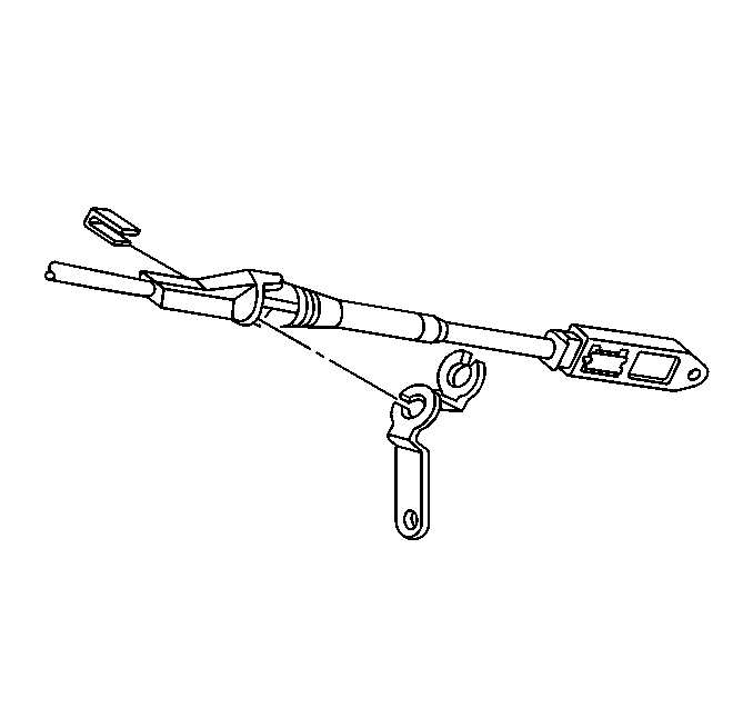
- Install the shift control
cable bracket to the shift control cable, if removed.
| 1.1. | Slide the smaller diameter portion of the cable into the slot
in the shift cable bracket. |
| 1.2. | Push the tabs through the hole in the bracket to lock the cable
in place. |
| 1.3. | Insert the shift cable retaining staple clip between the shift
cable retaining tabs. |
Press the staple clip firmly to secure.
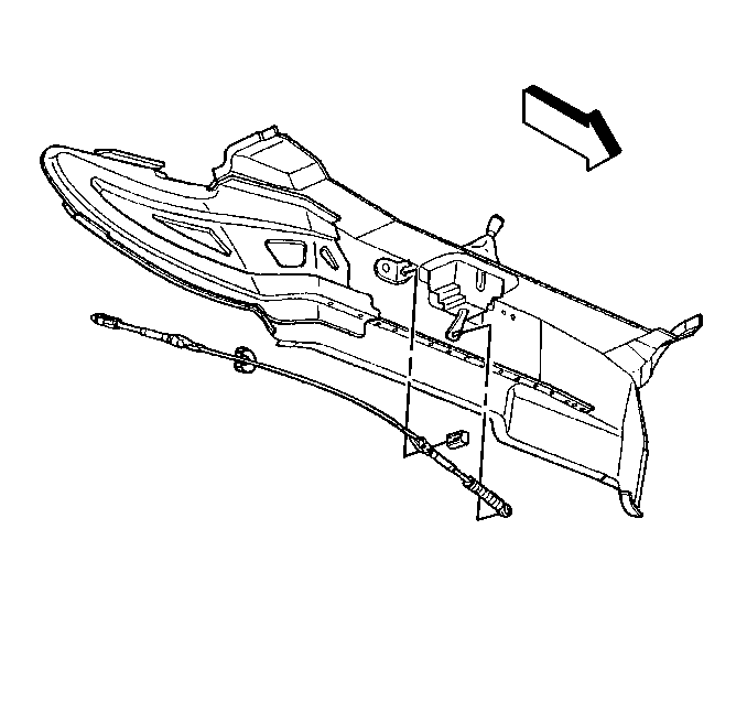
- Position and install the
shift control cable to the driveline tunnel bracket.
| 2.1. | Slide the smaller diameter portion of the shift cable into the
slot in the driveline tunnel bracket. |
| 2.2. | Push the shift cable retaining tabs through the hole in the bracket
to lock the cable in place. |
| 2.3. | Insert the shift cable retaining staple clip between the shift
cable retaining tabs. |
Press the staple clip firmly to secure.
- Align the shift control cable end to the floor shift control arm
stud.
Important: Use care to not suddenly jerk the shift control cable during assembly,
the shift control cable rod end guide tubes are EXTREMELY INFLEXIBLE and capable
of only a SLIGHT bend.
- CAREFULLY secure the shift control cable end clip to the floor shift
control arm stud.
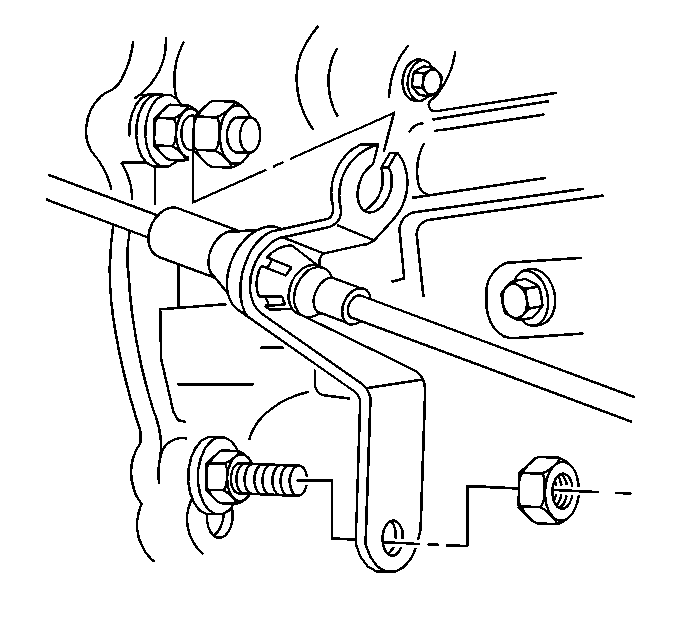
- Install the shift control
cable bracket to the transmission studs.
Notice: Use the correct fastener in the correct location. Replacement fasteners
must be the correct part number for that application. Fasteners requiring
replacement or fasteners requiring the use of thread locking compound or sealant
are identified in the service procedure. Do not use paints, lubricants, or
corrosion inhibitors on fasteners or fastener joint surfaces unless specified.
These coatings affect fastener torque and joint clamping force and may damage
the fastener. Use the correct tightening sequence and specifications when
installing fasteners in order to avoid damage to parts and systems.
- Install the nuts
retaining the shift control cable bracket to the transmission.
Tighten
Tighten the transmission shift control cable bracket retaining nuts
to 20 N·m (15 lb ft).
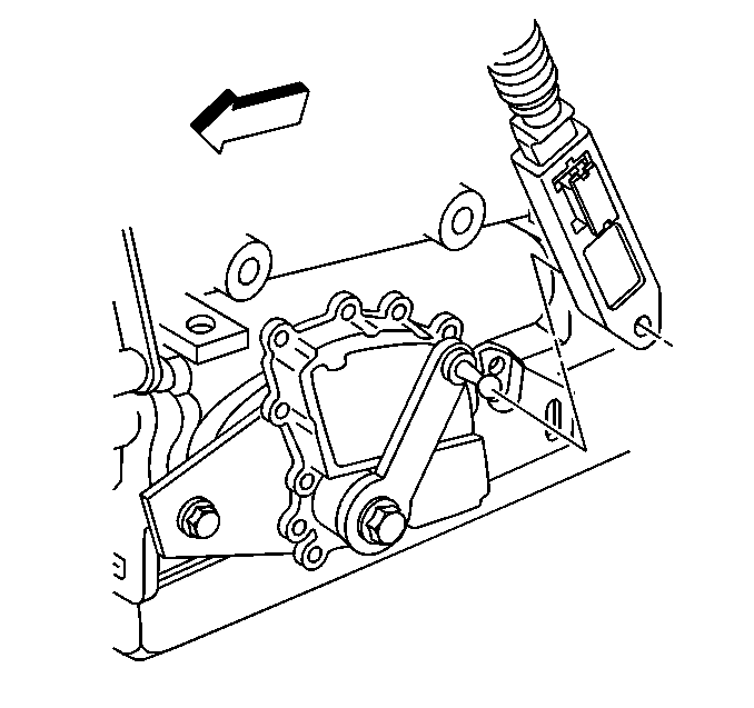
- Check to be sure that
BOTH the floor shift control and the transmission are in NEUTRAL.
- Align the shift control cable end to the transmission shift lever
stud.
Important: Use care to not suddenly jerk the shift control cable during assembly,
the shift control cable is EXTREMELY INFLEXIBLE.
- CAREFULLY secure the shift control cable end clip to the transmission
shift lever stud.
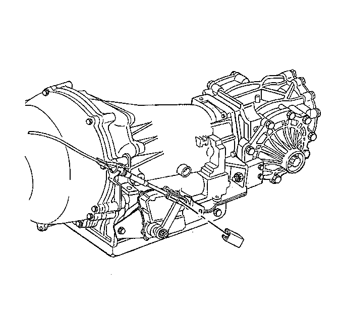
- If installing a NEW transmission
shift control cable, remove the shipping guard from the adjuster lock.
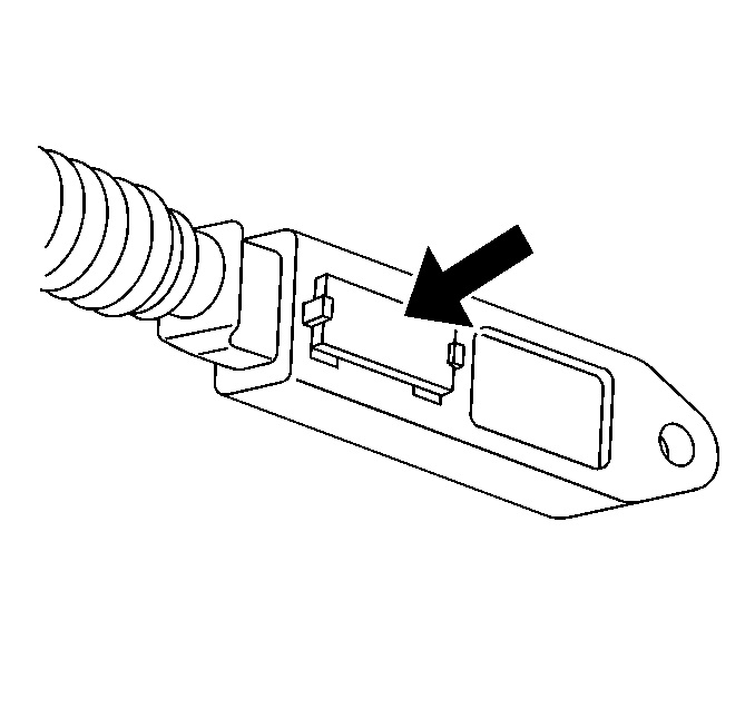
- If installing a NEW transmission
shift control cable, depress the shift control cable adjuster lock.
- Lower the vehicle; leave the vehicle on the hoist.
- Verify that the shift control cable is operating smoothly:
| 13.1. | Firmly apply the parking brake. |
| 13.2. | Turn the ignition switch to ON; DO NOT start the engine. |
| 13.3. | Apply the regular brakes. |
| 13.4. | Shift from NEUTRAL to FIRST, then shift from FIRST to SECOND,
then DRIVE and so on; pause for 1 second in each detent position. |
Take note of an audible sound from the transmission shift lever each
time a shift detent is selected.
| 13.5. | Shift from PARK directly to FIRST. |
| 13.6. | Repeat steps 13.4 and 13.5 an additional
2 times. |
| 13.7. | If any binding is felt during this check, or if no audible sound
was produced from the transmission shift lever, inspect the shift control
cable for damage (at either end of the cable). |
| 13.8. | Shift the floor shift control into PARK. |
| 13.9. | Release the regular brakes. |
| 13.10. | Turn the ignition switch OFF. |
| 13.11. | Release the parking brake. |
- Raise and support the vehicle.
- Install the driveline tunnel closeout panel. Refer to
Floor Panel Tunnel Panel Reinforcement Replacement
in Propeller
Shaft.
- Install the intermediate exhaust pipe. Refer to
Intermediate Pipe Replacement
in Engine Exhaust.
Caution: Road test a vehicle under safe conditions and while obeying all traffic laws.
Do not attempt any maneuvers that could jeopardize vehicle control. Failure to adhere
to these precautions could lead to serious personal injury and vehicle damage.
- Test drive
the vehicle in an area with little traffic; ensure that the transmission will
shift smoothly into, and maintain each detent position.


