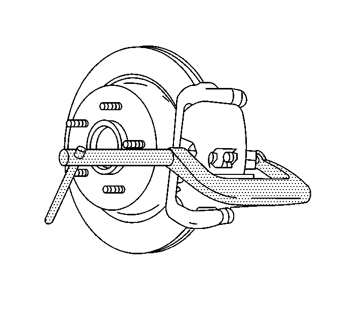
Removal Procedure
Tools Required
J 42450-A Hub Cleaning Kit
- Raise the vehicle and support. Refer to Lifting and Jacking the Vehicle in General Information.
- Remove the tire and wheel assembly. Refer to Tire and Wheel Removal and Installation in Tires and Wheels.
- Depress the piston into the brake caliper housing to provide clearance between the brake pads and the brake rotor. When using depressing the piston some fluid should be removed from the master cylinder.
- Remove the brake caliper mounting bracket bolts and discard.
- Remove the brake caliper mounting bracket and the caliper as a unit and support it to the vehicle so there is no weight on the brake hose.
- Disconnect the park brake cable from the apply lever.
- Remove the brake rotor.

Caution: Do not place your fingers in front of the piston in order to catch or protect the piston while applying compressed air. This could result in serious injury.
Caution: These fasteners MUST be replaced with new fasteners anytime they become loose or are removed. Failure to replace these fasteners after they become loose or are removed may cause loss of vehicle control and personal injury.


Important:
• Never operate the parking brake with the rotor removed. • Do not force the rotor off. If the rotor is difficult to remove,
ease it off by gently rotating it as you pull outward.

Installation Procedure
- Adjust the parking brake shoe to drum clearance. Refer to Parking Brake Shoe Replacement in Parking Brake.
- Clean the metal surfaces between the brake rotor and the hub bearing flange.
- Install the brake rotor.
- Install the disc brake caliper mounting bracket and the brake caliper as a unit.
- Install NEW brake caliper mounting bracket bolts.
- Install the tire and wheel assembly. Refer to Tire and Wheel Removal and Installation in Tires and Wheels.
- Lower the vehicle.
- Check the fluid level.
- With the engine running, pump the brake pedal slowly and firmly to seat the brake pads.
- Burnish the brakes as necessary. Refer to Brake Pad and Rotor Burnishing .

Notice: Whenever the brake rotor has been separated from the wheel bearing flange, clean any rust or foreign material from the mating surface of the rotor and flange with the J 42450 hub cleaning kit. Failure to do this may result in increased lateral runout of the rotor and brake pulsation.

Notice: Use the correct fastener in the correct location. Replacement fasteners must be the correct part number for that application. Fasteners requiring replacement or fasteners requiring the use of thread locking compound or sealant are identified in the service procedure. Do not use paints, lubricants, or corrosion inhibitors on fasteners or fastener joint surfaces unless specified. These coatings affect fastener torque and joint clamping force and may damage the fastener. Use the correct tightening sequence and specifications when installing fasteners in order to avoid damage to parts and systems.
Tighten
Tighten the brake caliper mounting bracket bolts to 175 N·m
(129 lb ft).
Tighten
Tighten the wheel nuts in sequence to 140 N·m (100 lb ft).
Caution: Do not move the vehicle until a firm brake pedal is obtained. Air in the brake system can cause the loss of brakes with possible personal injury.
