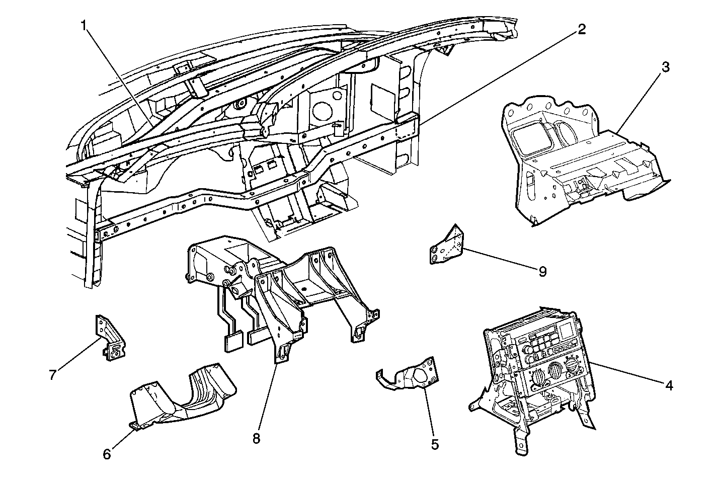
| Figure 1: |
Instrument Panel Structure Primary Components

|
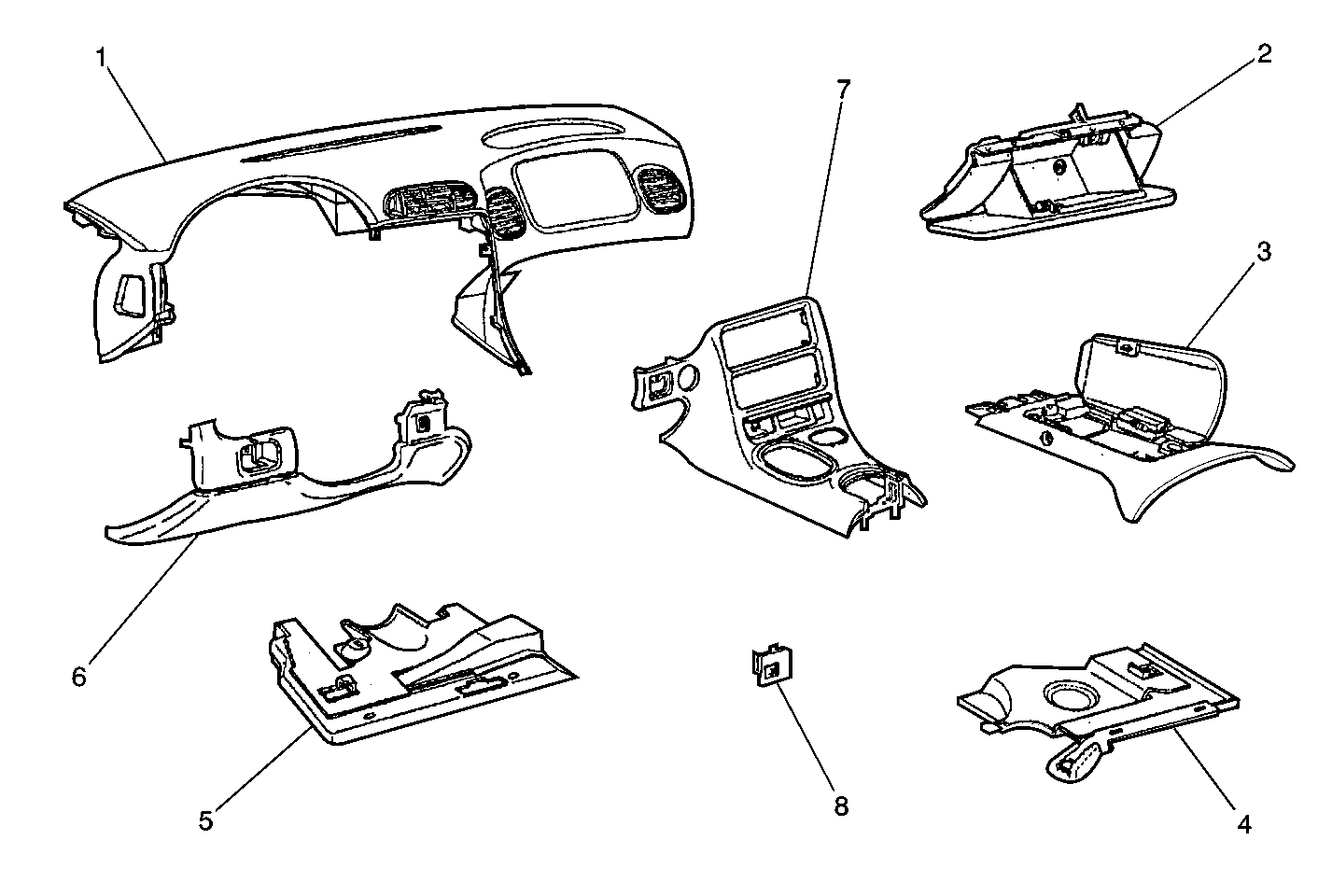
| Figure 2: |
Instrument Panel Trim Primary Components

|
The
Corvette instrument panel (I/P) structure is made up of seven brackets, which
are fastened to two I/P support beams spanning the width of the door hinge
pillars. This I/P structure is assembled at the plant in a locating fixture
to assure that both the structure and the attaching trim will be aligned properly,
which in turn yields an extremely solid, quiet and high quality fitting I/P.
To accomplish this design and build method, the I/P brackets do not
incorportate as many net locating holes as a common I/P. If the I/P brackets
are to be removed for service, the location of the bracket(s) must be marked
prior to removal in order to assure proper alignment upon installation. Proper
alignment of the brackets to the original build locations, provide proper
trim fits. For instructions on marking I/P bracket locations, refer to
Instrument Panel Disassembly Precautions
.


