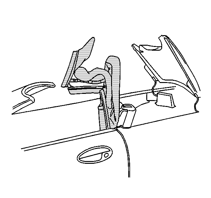
Removal Procedure
- Remove the seat belt upper guide.
- Remove the lock pillar upper trim.
- Position the number one and the number five bows in an up position.
- Disconnect the rear defogger electrical connections.
- Remove the bolts mounting the top to the pillar bracket.
- Slide the top slightly up and then rearward and out of the pillar bracket.


Installation Procedure
- Position the folded top to the vehicle with the top resting on the pillar bracket pin.
- Loosely install the bolts attaching the top to the bracket.
- Insert a tapered pin (scratch awl) through the hole in the top pivot bracket into the alignment hole in the pillar bracket to align the top.
- Tighten the mounting bolts.
- Remove the alignment tool.
- Close and latch the top.
- Connect the rear defogger electrical connections.
- Install the lock pillar trim.
- Install the seat belt upper guide.

Notice: Use the correct fastener in the correct location. Replacement fasteners must be the correct part number for that application. Fasteners requiring replacement or fasteners requiring the use of thread locking compound or sealant are identified in the service procedure. Do not use paints, lubricants, or corrosion inhibitors on fasteners or fastener joint surfaces unless specified. These coatings affect fastener torque and joint clamping force and may damage the fastener. Use the correct tightening sequence and specifications when installing fasteners in order to avoid damage to parts and systems.
Tighten
Tighten the folding top mounting bolts to 25 N·m (18 lb ft).


Tighten
Tighten the seat belt upper guide nut to 41 N·m (30 lb ft).
