At this point in the process of diagnosing the vibration;
the vibration has been duplicated and the frequency of the vibration has been
determined to be related to the tire and wheel rotating components group,
or vehicle speed sensitive.
(If these determinations have not yet been made, refer to
Classifying the Vibration
before proceeding.)
The following specific vehicle components will now be addressed according
to vibration frequency and symptoms:
Symptoms of Tire and Wheel Related Vibrations
The following are symptoms of vibrations caused by tire/wheel assemblies:
| • | The vibration is always vehicle-speed related. |
| | If the vibration is affected by the speed of the engine, or is eliminated
by placing the transmission in NEUTRAL, then the vibration is not related
to the tire/wheel assemblies, the brake rotors, the wheel hubs or the wheel
studs. |
| • | The vibration will feel like a shake, usually in the steering
wheel or the seat: |
| - | Tire and wheel vibrations that are felt in the steering wheel
are most likely related to the front tire/wheel assemblies. |
| - | Tire and wheel vibrations that are felt in the seat or the floor
are most likely related to the rear tire and wheel assemblies. |
| - | This may not always hold true, but is a general rule that may serve
to initially isolate a problem to the front or the rear of the vehicle. |
| • | The customer may complain of a waddle at low speeds of 8 to 56 km/h
(5 to 35 mph). |
| • | The frequency on the Smart Electronic Vibration Analyzer J38792-50
(Smart EVA) will correspond to an order (first, second, third, etc.) of tire
rotation. |
| • | The frequency of the most common order, first-order will usually
be in the 10 to 20 Hz range, depending on the speed of
the complaint and the size of the tire. The smaller the tire, the faster
it will rotate at any given speed. |
| • | First-order tire vibrations rarely produce audible noise; due
to the fact that the range of hearing in the human ear begins at 20 Hz,
and most first-order tire vibrations produce a frequency of 10 to 20 Hz.
The exception to this would be if the tires display an irregular tread pattern
or flat spots, causing a growling or slapping noise. |
Diagnosis of Tire and Wheel Related Vibrations
A first order tire and wheel vibration is usually the result of one
of the following five conditions:
| • | Excessive radial runout |
| • | Excessive lateral runout |
| • | Excessive radial force variation |
| • | Excessive lateral force variation |
These conditions must be eliminated one at a time in order to attain
a set of tires that are free from vibration causing elements. Substitute a
set of tires from another vehicle ONLY as a last resort, and ONLY after
the tires have been tested on a similar vehicle under the same conditions.
Correcting the existing tire and wheel assemblies is the most accurate
and least time consuming approach. This is due to vehicle-to-vehicle sensitivities
and the differences between the hubs of any two vehicles.
Important: In order to avoid back-tracking and/or unnecessary repairs, proceed
through the diagnosis of tire and wheel assembly vibrations step by step and
in order as called out by each step.
Visual Inspection
Prior to removing the tire and wheel assemblies from the vehicle, perform
the following visual inspections:
- Inspect the front and rear suspension components for wear and/or
damage. Replace worn or damaged parts as necessary, then perform a wheel alignment
as necessary.
- Check the tire inflation pressures. Adjust the tire inflation
pressures to specifications if necessary.
- Closely inspect the tires for the following conditions:
| • | Tread distortions or separations |
| • | Sidewall bulges; possible impact damage (slight sidewall indentations
are normal ply splices) |
- If any of the tires exhibit any of these conditions, replace the
worn or damaged tire(s).
- Closely inspect the wheel rim flanges for any signs of impact
damage and for loose or missing wheel weights.
If any or the wheels exhibit severe damage, replace the damaged wheel(s).
- If any of the tires and/or wheels were replaced, proceed to Off-Vehicle
Runout Check, below.
- If NO excessive wear, unusual wear, or damage was found in any
of the components inspected, proceed to On-Vehicle Runout Check, below.
On-Vehicle Runout Check
If the vehicle has been sitting in one place for an extended period
of time, the tires may develop flat spots at the point where the tires were
resting on the ground. These flat spots will affect the runout readings.
In order to eliminate these flat spots, drive the vehicle long enough to
warm up the tires. The flat spots must be eliminated prior to taking any
runout measurements.
Prior to removing the tire and wheel assemblies from the vehicle, perform
the following:
- Closely inspect each tire for proper and even bead seating.
- If any of the tire beads are not properly or evenly seated, reseat
the tire bead (refer to
Tire Mounting and Dismounting
, or
Tire Mounting and Dismounting
in
Tires and Wheels), then proceed to step 3.
- Prepare the vehicle and measure the runout of each tire and wheel
assembly, refer to
Tire and Wheel Runout Measurement
.
- If the on-vehicle runout measurement of the tire and wheel assemblies
ARE within specifications, proceed to
Tire and Wheel Balancing
.
- If the on-vehicle runout measurement of the tire and wheel assemblies
ARE NOT within specifications, proceed to Off-Vehicle Runout Check, below.
Off-Vehicle Runout Check
If the vehicle has been sitting in one place for an extended period
of time, the tires may develop flat spots at the point where the tires were
resting on the ground. These flat spots will affect the runout readings.
In order to eliminate these flat spots, drive the vehicle long enough to
warm up the tires. The flat spots must be eliminated prior to taking any
runout measurements.
- Prior to removing the tire and wheel assemblies from the vehicle,
mark the location of the wheels to the wheel studs and mark the specific vehicle
position on each tire and wheel (LF, LR, RF, RR).
- Remove the tire and wheel assemblies from the vehicle.
- Closely inspect each tire for proper and even bead seating.
- If any of the tire beads are not properly or evenly seated, reseat
the tire bead (refer to
Tire Mounting and Dismounting
, or
Tire Mounting and Dismounting
in Tires and Wheels),
then proceed to step 5.
- Measure the runout of each tire and wheel assembly, refer to
Tire and Wheel Runout Measurement
.
- If the off-vehicle runout measurement of the tire and wheel assemblies
ARE within specifications, proceed to Tire and Wheel Mounting Inspection,
below.
- If the off-vehicle runout measurement of the tire and wheel assemblies
ARE NOT within specifications, replace the tire(s) and/or wheel(s) as determined
during the measurement, then recheck the runout to ensure that the tire and
wheel assembly (assemblies) is (are) now within specifications, then proceed
to step 8.
- Balance the tire and wheel assembly (assemblies) which have had
runout corrected and brought to within specifications. Refer to
Tire and Wheel Balancing
.
Tire and Wheel Mounting Inspection
On-vehicle imbalance may result from components other than the tire
and wheel assemblies -- hubs, rotors, drums -- having imbalance.
It may be necessary to perform an on-vehicle, high-speed balance, or to replace
the components suspected of being the cause.
Checking Rear Rotor Imbalance (On-Vehicle)
- Support the vehicle rear (driving) axle on a suitable hoist or
jackstands. Refer to
Lifting and Jacking the Vehicle
in General Information.
- Remove the rear tire and wheel assemblies. Refer to
Tire and Wheel Removal and Installation
in Tires
and Wheels.
- Reinstall the wheel nuts in order to retain the rotors.
Caution: One or more of the following guidelines may apply when performing specific required tests in the work stall:
| • | When a test requires spinning the drive wheels with the vehicle jacked up, adhere to the following precautions: |
| - | Do not exceed 56 km/h (35 mph) when spinning one drive wheel with the other drive wheel stopped. This limit is necessary because the speedometer indicates only one-half the actual vehicle speed under these conditions. Personal injury
may result from excessive wheel spinning. |
| - | If all of the drive wheels are spinning at the same speed, do not exceed 112 km/h (70 mph). Personal injury may result from excessive wheel spinning. |
| - | All persons should stay clear of the rotating components and the balance weight areas in order to avoid possible personal injury. |
| - | When running an engine in the repair stall for an extended period of time, use care not to overheat the engine and the transmission. |
| • | When a test requires jacking up the vehicle and running with the wheels and brake rotors removed, adhere to the following precautions: |
| - | Support the suspension at normal ride height. |
| - | Do not apply the brake with the brake rotors removed. |
| - | Do not place the transmission in PARK with the drive axles spinning. |
| - | Turn Off the ignition in order to stop the powertrain components from spinning. |
| • | When running an engine in the work stall, use the exhaust removal system to prevent breathing dangerous gases. |
- Run
the vehicle at the complaint speed, and note if the vibration is still present.
| 4.1. | If the vibration is still present, remove the rear rotors and
run the vehicle back up to the complaint speed. |
| 4.2. | If the vibration is eliminated when the rotors are removed from
the vehicle, perform the test with one rotor at a time. Replace the rotor
which is causing the vibration. |
Always check the new rotor for imbalance.
Checking Rotor Imbalance (Off-Vehicle)
Most brake rotors may be checked for imbalance using an off-vehicle
balancer.
- Measure the diameter and the width of the rotor.
- Mount the rotor on a balancer in the same manner as a wheel.
Important: The rotors can be checked for STATIC imbalance ONLY. Ignore the dynamic
imbalance readings.
- Inspect the brake rotor for static imbalance.
There is not a set tolerance for rotor (or drum) static imbalance. (However,
any brake drum/rotor measured in this same manner which is over ¾ ounce
may have the potential to cause a vibration.) Rotors suspected of causing
a vibration should be replaced. The new rotor should be checked for imbalance
in the same manner.
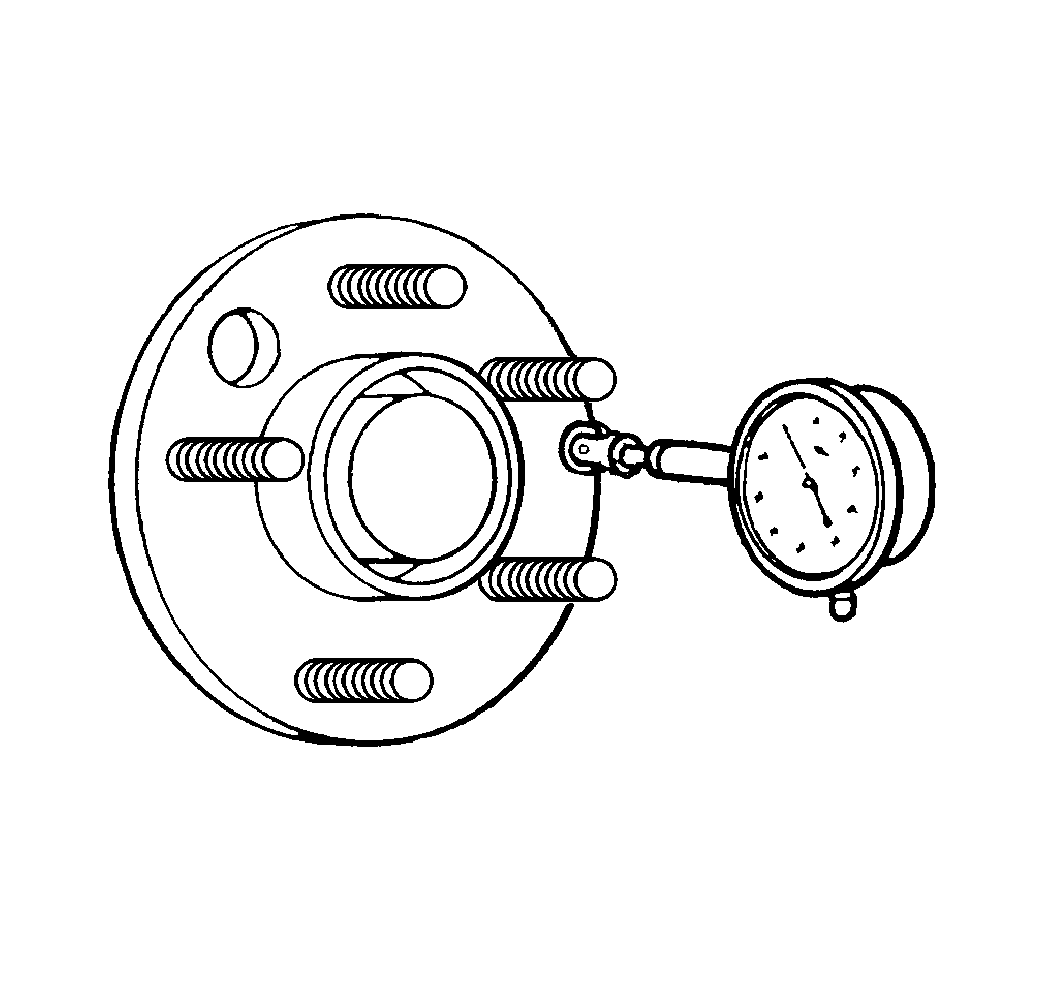
Wheel Hub/Axle Flange Runout Check
Inspect the wheel hub/axle flange runout when lateral runout occurs
during on-vehicle testing but not during off-vehicle testing. The tolerances
provided are only guidelines. Perform corrections only if the on-vehicle runout
cannot be brought to within tolerance.

- Position the dial indicator
on the machined surface of the hub, axle flange, or brake rotor, outside of
the wheel studs.
- Rotate the hub in order to find the low spot.
- Set the dial indicator to zero at the low spot.
- Rotate the hub again and check the total amount of runout.
Specification (Guideline)
Runout tolerance: 0.127 mm (0.005 in)
- If the runout of the wheel hub/axle flange is within specification,
proceed to Wheel Stud (Stud Circle) Runout Check, below.
- If the runout of the wheel hub/axle flange is marginal, the wheel
hub may or may not be the source of the vibration. Proceed to Radial/Lateral
Force Variation Check, below.
- If the runout of the wheel hub/axle flange is excessive, replace
the wheel hub/axle flange. Check the runout of the new wheel hub/axle flange.
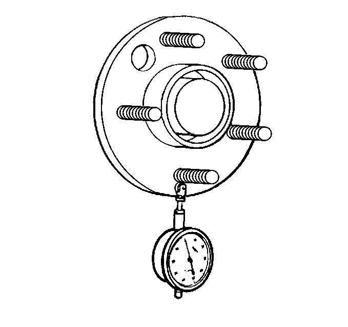
Wheel Stud (Stud Circle) Runout Check
Use the following procedure whenever the off-vehicle radial runout and
the on-vehicle radial runout are significantly different, and earlier attempts
to correct the tire and wheel vibration condition have not been successful.

- Position the dial indicator
in order to contact the wheel mounting studs.
Measure the stud runout as close to the flange as possible.
- Turn the hub to register on each of the wheel studs.
- Zero the dial indicator on the lowest stud.
- Rotate the hub again and check the total amount of runout.
Specification (Guideline)
Runout tolerance: 0.254 mm (0.010 in)
- If the runout of the wheel studs is within specification, proceed
to Radial/Lateral Force Variation Check, below.
- If the runout of the wheel studs is marginal, the wheel studs
may or may not be contributing to the vibration. Proceed to Radial/Lateral
Force Variation Check, below.
- If the runout of the wheel hub/axle flange is excessive, replace
the wheel studs as necessary. Check the runout of the new wheel studs.
Radial/Lateral Force Variation Inspection
Force variation refers to a radial or lateral movement of the tire and
wheel assembly which acts much like runout, however, force variation has to
do with variations in the construction of the tire which may actually cause
vibration in a vehicle, even though the tire and wheel assembly runout and
balance are within specifications.
Due to tighter tolerances and higher standards in manufacturing, these
instances are becoming rare.
The most effective way to minimize the possibility of force variation
as a factor in tire and wheel assembly vibration is to ensure that the tire
and wheel assembly runout is at an absolute minimum (this tire and wheel vibration
diagnostic process, if followed correctly, has already ruled-out runout and
balance as contributing factors to the vibration).
Radial Force Variation Check

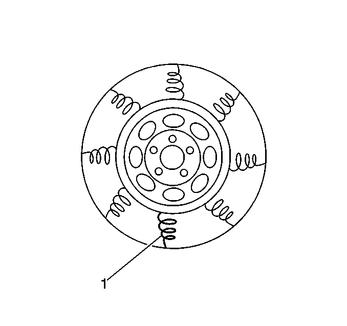
Radial force variation
refers to the difference in the stiffness of a tire sidewall as the tire rotates
and contacts the road. Tire and wheel assemblies have some stiffness due to
splices in the different plies of the tire, but these stiffness differences
do not cause a problem unless the force variation is excessive. These stiff
spots (1) in the tire sidewall can deflect the tire and wheel assembly upward
as the assembly contacts the road.
| • | If there is only one stiff spot in a tire sidewall, the stiff
spot will deflect the spindle once per revolution of the tire and wheel assembly,
causing a first-order tire and wheel vibration. |
| • | If there are two stiff spots in a tire sidewall, the stiff spots
can cause a second-order vibration. |
First- and second-order tire and wheel vibrations are the most common
to occur as a result of radial force variation. Higher orders (third, fourth,
etc.) are possible but rarely occur.
The following is the best method available to aid in determining if
radial force variation is a factor in the vehicle tire and wheel vibration:
- Substitute a set of known good tire and wheel assemblies (of the
same size and type) for the suspected (original) assemblies. Refer to
Tire and Wheel Removal and Installation
in Tires and Wheels.
- Road test the vehicle to determine if the vibration is still present.
Refer to
Road Test
.
- If the vibration is still present, proceed to Wheel Alignment
Check, below.
- If the vibration is eliminated, install one of the original tire
and wheel assemblies, using the matchmarks made prior to removal (refer to
Tire and Wheel Removal and Installation
in Tires and Wheels), then road test the vehicle to determine if the
vibration has returned. Refer to
Road Test
.
- Continue the process of installing the original tire and wheel
assemblies one at a time, then road testing the vehicle, until the tire and
wheel assembly (assemblies) which are causing the vibration have been identified.
- Replace the tire(s) on the vibration causing tire and wheel assembly
(assemblies). Refer to
Tire Mounting and Dismounting
, or
Tire Mounting and Dismounting
in Tires and Wheels.
- Road test the vehicle to verify that the vibration has been eliminated.
Refer to
Road Test
.
If some vibration is still present, proceed to Wheel Alignment Check,
below.
Lateral Force Variation Check

Lateral force variation refers to the difference in the stiffness or
conformity of the belts within a tire as the tire rotates and contacts the
road. Tire belts have may have some stiffness or conformity differences, but
these differences do not cause a problem unless the force variation is excessive.
These variations in the belts of the tire can deflect the vehicle sideways
or laterally. (A shifted belt inside a tire may cause lateral
force variation.)
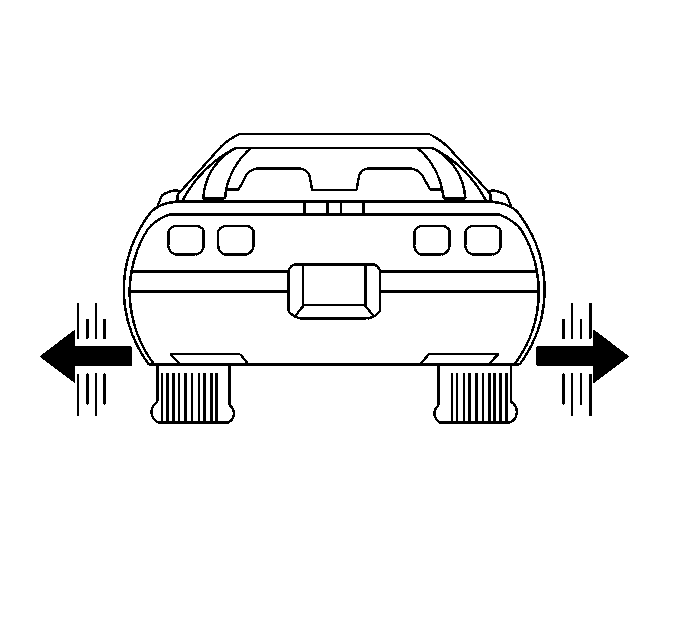
In most cases where excessive lateral force variation exists, the vehicle
will display a wobble or waddle at low speeds (8 to 40 km/h
[5 to 25 mph]) on a smooth road surface. This condition
is usually related to first-order tire and wheel vibration.
The following is the best method available to aid in determining if
lateral force variation is a factor in the vehicle tire and wheel vibration:
- Substitute a set of known good tire and wheel assemblies (of the
same size and type) for the suspected (original) assemblies. Refer to
Tire and Wheel Removal and Installation
in Tires and Wheels.
- Road test the vehicle to determine if the vibration is still present.
Refer to
Road Test
.
- If the vibration is still present, proceed to Wheel Alignment
Check, below.
- If the vibration is eliminated, install one of the original tire
and wheel assemblies, using the matchmarks made prior to removal (refer to
Tire and Wheel Removal and Installation
in Tires and Wheels), then road test the vehicle to determine if the
vibration has returned. Refer to
Road Test
.
- Continue the process of installing the original tire and wheel
assemblies one at a time, then road testing the vehicle, until the tire and
wheel assembly (assemblies) which are causing the vibration have been identified.
- Replace the tire(s) on the vibration causing tire and wheel assembly
(assemblies). Refer to
Tire Mounting and Dismounting
, or
Tire Mounting and Dismounting
in Tires and Wheels.
- Road test the vehicle to verify that the vibration has been eliminated.
Refer to
Road Test
.
If some vibration is still present, proceed to Wheel Alignment Check,
below.
Wheel Alignment Check
- Inspect the front and rear wheel alignment. Refer to
Wheel Alignment Measurement
and
Wheel Alignment Measurement
in Wheel Alignment.
- If the front and rear wheel alignment is within specifications,
proceed to Balancing Tires and Wheels (On-Vehicle), below.
- If the wheel alignment is out of specifications, adjust the wheel
alignment to within specifications. Refer to the following procedures as required:
- Road test the vehicle to determine if the vibration is still present.
Refer to
Road Test
.
- If the vibration is still present, proceed to Balancing Tires
and Wheels (On-Vehicle), below.
Balancing Tires and Wheels (On-Vehicle)
If after following this tire and wheel vibration diagnostic process,
some amount of tire and wheel vibration is still evident, an on-vehicle high-speed
spin balancer may be used (to perform an on-vehicle balance) in an attempt
to finish balance the tire and wheel assemblies, wheel hubs and brake rotors
simultaneously. On-vehicle balancing can also compensate for minor amounts
of residual runout encountered as a result of mounting the tire and wheel
assembly on the vehicle, as opposed to the balance which was achieved on
the off-vehicle balancer.
If on-vehicle balancing is decided upon as an option, carefully consider
the following information before proceeding:
| • | Vehicles equipped with low profile, wide tread path, high performance
tires and wheels are susceptible to small amounts of dynamic imbalance. |
| • | If performing an on-vehicle balance, great care must be taken
when placing the wheel balance weights on the wheels. If the wheel balance
weights are not placed accurately, they can actually induce dynamic imbalance
and thus increase the severity of the vibration. |
| • | Inspect the vehicle wheel bearings to ensure that they are in
good condition. |
| • | Thoroughly inspect all on-vehicle balancing equipment and ensure
that the equipment is fully within the manufacturer's recommended specifications. |
In order to perform an on-vehicle balancing procedure, carefully follow
the manufacturer's specific instructions while keeping the following tips
in mind:
| • | Do not remove the off-vehicle balance weights. The purpose of
on-vehicle balance is to fine tune the assembly balance already achieved,
not to start over. |
| • | Leave all wheel trim installed whenever possible. |
| • | If the on-vehicle balance calls for more than 1 ounce of
additional weight, split the weight between the inboard and outboard flanges
of the wheel, so as to not upset the dynamic balance of the assembly achieved
in the off-vehicle balance. For wheel balance weight information, refer to
Wheel Weight Usage
. |
| • | If available, tape-off an area on top of the fenders and the quarter
panels, then place the vibration sensor of the Smart Electronic Vibration
Analyzer (Smart EVA) on the fender or quarter panel above the specific tire
and wheel assembly while it is being on-vehicle balanced. |
| | The Smart EVA will provide a visual indication of the amplitude
of the vibration, and the effect that the on-vehicle balance has on it. |
After completion of the on-vehicle balance, road test the vehicle to
determine weather the vibration has been eliminated. Refer to
Road Test
.


