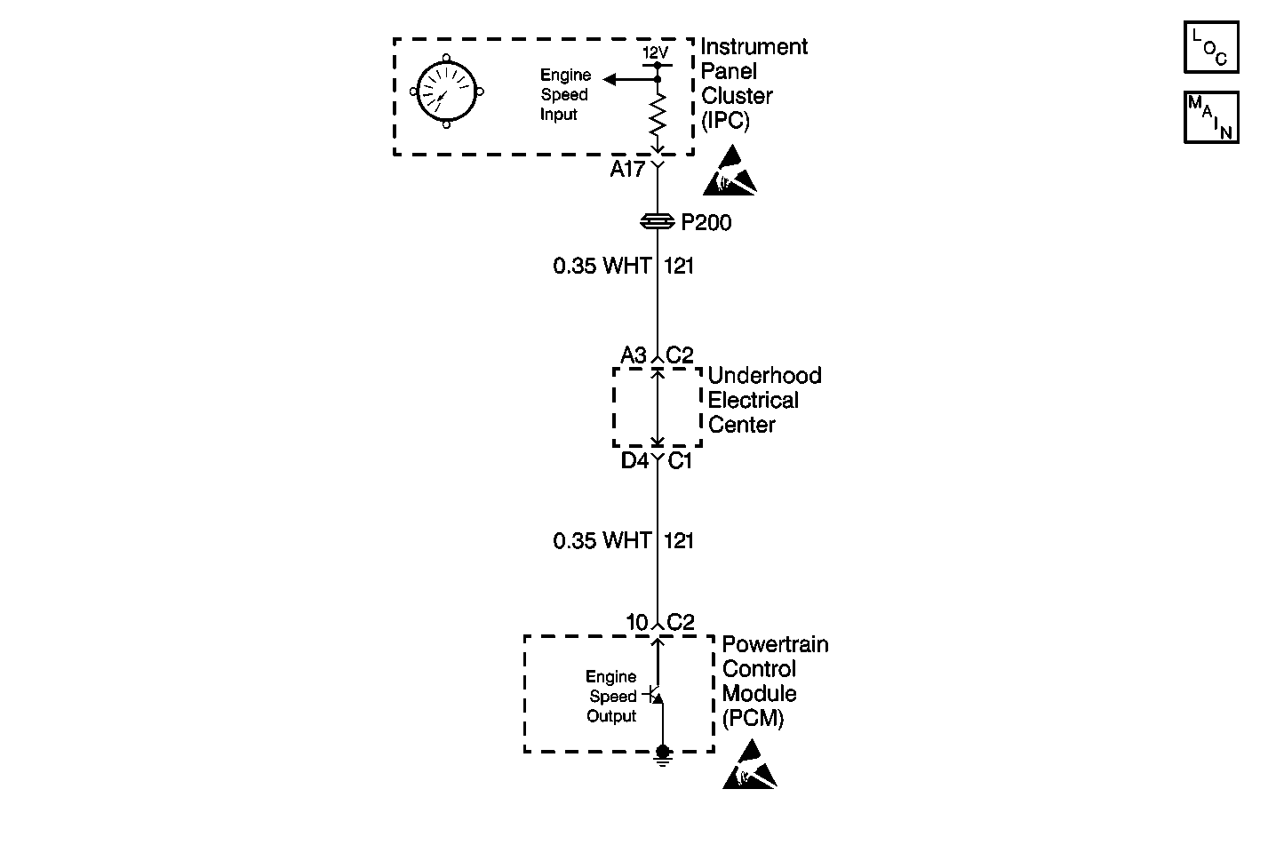
Circuit Description
The Instrument Panel Cluster (IPC) receives engine RPM information from the Powertrain Control Module (PCM). Engine RPM input information is obtained from the PCM on a dedicated engine speed input to the IPC. The IPC also receives engine RPM data on the serial data line. The PCM is responsible for processing and sending engine RPM data to the IPC. The IPC will only display the engine RPM data that was sent by the PCM. The IPC monitors the engine RPM output information sent from the PCM for an out of range condition.
Conditions for Setting the DTC
| • | The IPC detects engine RPM information sent from the PCM over 7400 RPM. |
| • | Condition must be present for 1 second. |
Action Taken When the DTC Sets
| • | Stores a DTC B0521 in the IPC memory. |
| • | The IPC will display engine RPM at 7400 RPM. |
| • | No driver warning message will be displayed for this DTC. |
Conditions for Clearing the DTC
| • | The IPC detects engine RPM information sent from the PCM under 7400 RPM. |
| • | A history DTC will clear after 50 consecutive ignition cycles if the condition for the malfunction is no longer present. |
| • | Use the IPC clear DTC feature. |
| • | Use a scan tool. |
Diagnostic Aids
| • | The following conditions may cause an intermittent malfunction to occur: |
| - | The PCM is unable to process the correct RPM data. |
| - | Intermittent or erratic RPM signal sent from the PCM. |
| • | Test drive the vehicle and check for proper tachometer operation. If the IPC is unable to display the proper engine RPM, use a scan tool to display the PCM engine RPM data. If the PCM is not sending the proper engine RPM data to the IPC, then the PCM and engine RPM circuit must be diagnosed first before diagnosing the IPC. |
| • | Always check for proper tachometer circuit operation by displaying PCM engine RPM data and checking for stored VSS DTCs with a scan tool before attempting to diagnose a DTC B0521. |
| • | If the DTC is a history DTC, the problem may be intermittent. Perform the tests shown while moving related wiring and connectors. This can often cause the malfunction to occur. |
Test Description
The numbers below refer to the step numbers on the diagnostic table:
-
This test checks for PCM engine speed (tachometer) DTC P0654 stored in the PCM memory. A PCM engine speed DTC P0654 will cause a DTC B0521 to set in the IPC memory. The PCM malfunction must first be diagnosed and corrected before diagnosing the IPC.
-
This test checks for proper tachometer operation. A tachometer malfunction will cause a DTC B0521 to set in the IPC memory. Always diagnose and correct any tachometer malfunctions before diagnosing a DTC B0521.
Step | Action | Value(s) | Yes | No |
|---|---|---|---|---|
1 | Were you sent here from the IPC Diagnostic System Check? | -- | ||
Using a scan tool, check for PCM engine speed (tachometer) DTC P0654. Is DTC P0654 stored in the PCM memory? | -- | |||
Road test vehicle and check for proper tachometer operation. Does the tachometer function properly? | -- | Go to Gauge System Check | ||
4 | Check the tachometer circuit for an intermittent malfunction. Refer to Diagnostic Aids. Was a problem found and repaired? | -- | ||
5 |
Does DTC B0521 set as current? | -- | System OK | |
6 | Replace the Instrument panel cluster. Refer to Instrument Cluster Replacement . Is the replacement complete? | -- | -- | |
7 |
Is the repair complete? | -- | -- |
