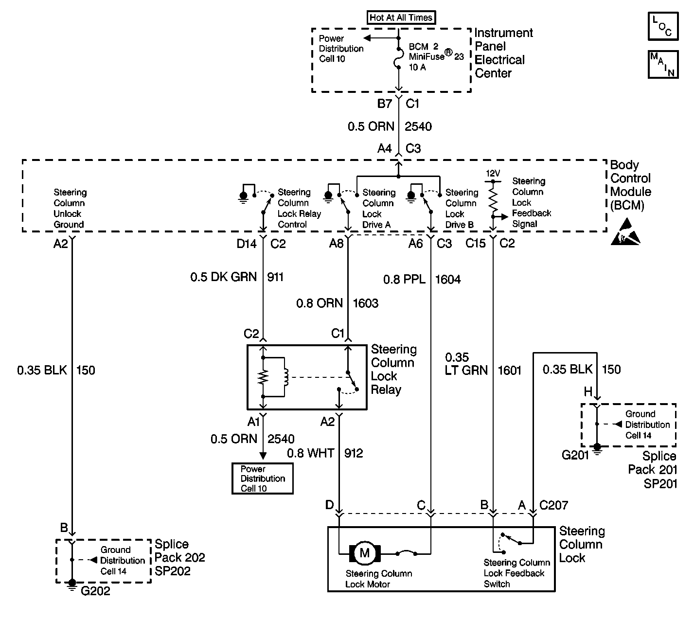
Circuit Description
The BCM provides the steering column control function which allows the column to be electronically locked or unlocked. The BCM provides two outputs, column lock drive (A) and column unlock drive (B) and a steering column lock relay control output. The BCM can apply a ground or battery output on the column lock drive (A) CKT 1603 or column unlock drive (B) CKT 1604 depending on the desired steering column lock motor position. The BCM uses the feedback switch in order to monitor the motor position and determine if the commanded position was accomplished.
The BCM controls the position of the steering column lock motor based on the following input information:
| • | Ignition position |
| • | Key IN ignition status |
| • | Key OUT of ignition status |
| • | Steering column lock feedback switch |
| • | PASS-Key® system |
| • | PCM password information |
| • | System voltage |
The BCM also monitors its circuitry for the column lock drive (A) circuit. If the BCM detects a malfunction present a DTC will set.
Conditions for Setting the DTC
| • | The BCM detects an internal malfunction (an open or a short to voltage) in the column lock drive (A) circuit. |
| • | There is an open in the BCM ground CKT 150. |
| • | The condition must be present for 100 ms. |
Action Taken When the DTC Sets
| • | Stores a DTC B2588 in the BCM memory. |
| • | The PCM may disable fuel if vehicle speed is detected over 2.4 km/h (1.5 mph). |
| • | Sends a message to the IPC to display the SERVICE COLUMN LOCK message. |
Conditions for Clearing the DTC
| • | The BCM no longer detects an internal malfunction (an open or a short to voltage) in the column lock drive (A) circuit. |
| • | There is no longer an open in the BCM ground CKT 150. |
| • | A history DTC will clear after 50 consecutive ignition cycles if the condition for the malfunction is no longer present. |
| • | Use the IPC clearing DTCs feature. |
| • | Use a scan tool. |
Diagnostic Aids
| • | The BCM grounds the steering column lock motor through CKT 150. If the BCM is unable to ground steering column lock motor through CKT 150, the BCM will set a DTC B2588. |
| • | Disconnecting the steering column connector C207 with the ignition in the ON position will cause the BCM to enter a Fail Enable Standby mode. The steering column will remain inoperative until the Fail Enable Standby mode is cleared. To clear this mode, disconnect the BCM fuse #25 for 15 seconds. |
| • | If the DTC is a history DTC, the problem may be intermittent. Perform the tests shown while moving related wiring and connectors. This can often cause the malfunction to occur. |
Test Description
The numbers below refer to the step numbers on the diagnostic table:
-
This test will for an open in the BCM ground CKT 150.
-
This test will check CKT 150 for an intermittent malfunction or poor connections.
Step | Action | Value(s) | Yes | No |
|---|---|---|---|---|
1 | Were you sent here from the BCM Diagnostic System Check? | -- | ||
Is the test light ON? | -- | |||
3 | Locate and repair open in CKT 150. Is the circuit repair complete? | -- | -- | |
Check the BCM connector C3 terminal A2 for an intermittent malfunction. Refer to Diagnostic Aids. Was an intermittent malfunction found and repaired? | -- | |||
5 |
Does DTC B2588 set as current? | -- | System OK | |
6 |
Is the replacement complete? | -- | -- | |
7 |
Is the repair complete? | -- | -- |
