Removal Procedure
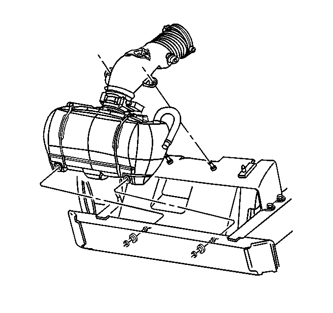
- Remove the air intake duct and air cleaner assembly.
- Remove the crankshaft balancer. Refer to Crankshaft Balancer Replacement .
- Drain the cooling system. Refer to Cooling System Draining and Filling in Engine Cooling.
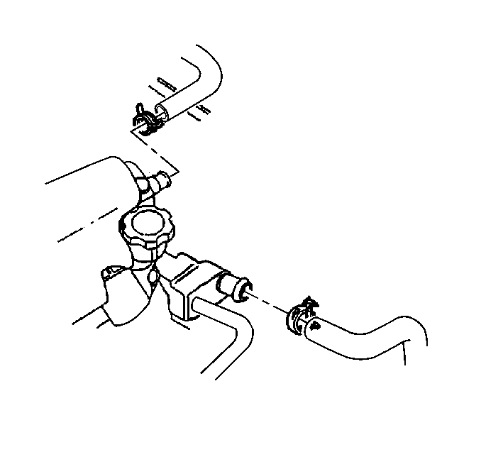
- Remove the radiator hoses from the water pump.
- Remove the heater hoses from the water pump.
- Remove the water pump, bolts and gaskets. Refer to Water Pump Replacement in Engine Cooling.
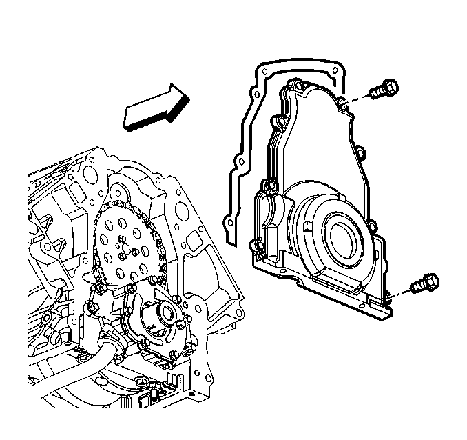
- Remove the front cover-to-engine block bolts.
- Remove the front cover-to-oil pan bolts.
- Remove the front cover and gasket.
- Discard the front cover gasket.
- Remove the crankshaft front oil seal from the cover.
- Discard the oil seal.


Important: Do not slide the front cover/gasket across the oil pan gasket or damage could result.
Installation Procedure
Tools Required
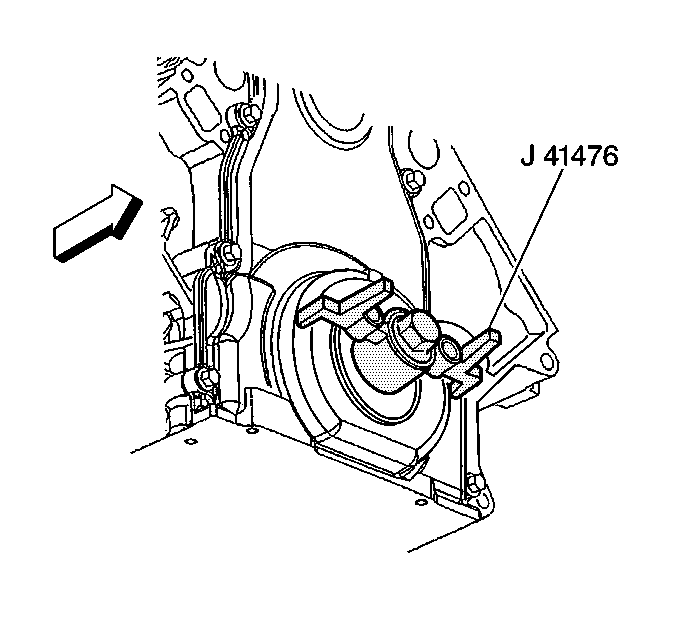
J 41476 Front/Rear Cover Alignment (Crankshaft Oil Seal Area)
Important:
• Do not reuse the crankshaft oil seal or front cover gasket. • Do not slide the front cover/gasket across the oil pan gasket. • The special tool in this procedure is used to properly align the
crankshaft front oil seal. • The crankshaft front oil seal MUST be centered in relation to
the crankshaft. • An improperly aligned front cover may cause premature front oil
seal wear and/or engine oil leaks.
- Apply a 5 mm (0.20 in) bead of sealant GM P/N 12378190 to the corner where the oil pan meets the engine block.
- Install the front cover, gasket and bolts on to the engine.
- Tighten the front cover bolts finger tight. Do not overtighten.
- Align the tapered legs of J 41476 with the machined alignment surfaces on the front cover.
- Install the crankshaft balancer bolt until sung. Do not overtighten.
- Install the oil pan-to-cover bolts until snug in order to position the cover at the pan rail.
- Tighten the oil pan-to-cover bolts in the following order:
- Tighten the oil pan-to-front cover bolts to 25 N·m (18 lb ft).
- Tighten the front cover bolts to 25 N·m (18 lb ft).
- Remove the J 41476 from the front cover.
- Install the front crankshaft oil seal. Refer toCrankshaft Front Oil Seal Installation .
- Install the crankshaft balancer. Refer to Crankshaft Balancer Replacement .
- Install the water pump, gaskets and bolts. Refer to Water Pump Replacement .
- Connect the heater hoses to the water pump.
- Connect the radiator hoses to the water pump.
- Install the air intake duct and air cleaner assembly.
- Fill the cooling system. Refer to Cooling System Draining and Filling in Engine Cooling.
- Check for leaks.


Notice: Use the correct fastener in the correct location. Replacement fasteners must be the correct part number for that application. Fasteners requiring replacement or fasteners requiring the use of thread locking compound or sealant are identified in the service procedure. Do not use paints, lubricants, or corrosion inhibitors on fasteners or fastener joint surfaces unless specified. These coatings affect fastener torque and joint clamping force and may damage the fastener. Use the correct tightening sequence and specifications when installing fasteners in order to avoid damage to parts and systems.
Tighten


