Removal Procedure
Important: The intake manifold, throttle body, fuel injection rail and fuel injectors may be removed as an assembly. If not servicing the individual components, remove the intake manifold as a complete assembly.
Tools Required
J 34730-1A Fuel Pressure Gauge
- Raise the vehicle and support. Refer to Lifting and Jacking the Vehicle in General Information.
- Drain the coolant system. Refer to Cooling System Draining and Filling in Engine Cooling.
- Lower the vehicle.
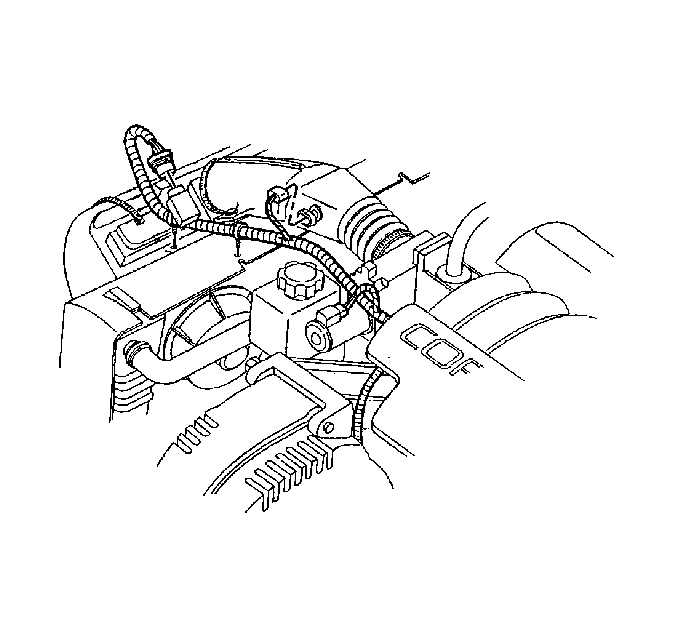
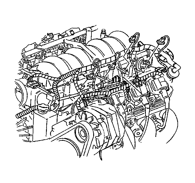
- Disconnect the intake air temperature (IAT) sensor connectors at both the air intake duct and the throttle body.
- Disconnect the mass air flow (MAF) sensor connector at both the air intake duct and the throttle body.
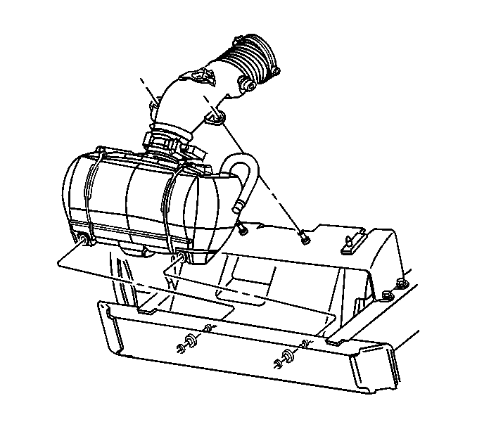
- Remove the air intake duct and air cleaner assembly.
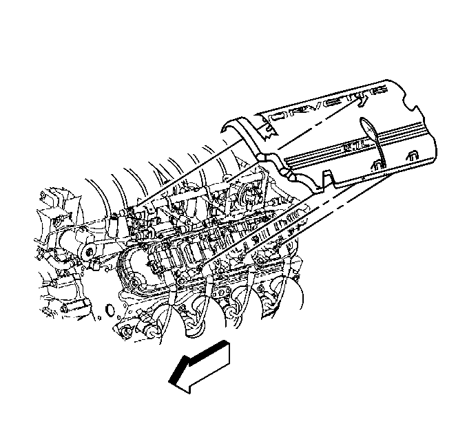
- Remove the fuel rail covers.
- Relieve the fuel system pressure using J 34730-1A . Refer to Fuel Pressure Relief in Engine Controls - 5.7 L.
- Disconnect the fuel line from the fuel rail.
- Remove the vacuum ventilation hoses.
- Disconnect the fuel injector wire harness electrical connectors.
- Disconnect the throttle position sensor connector.
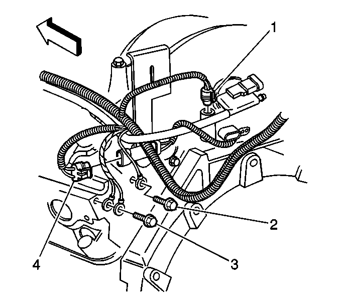
- Disconnect the knock sensor electrical connector (4).
- Disconnect all the remaining electrical connections from the intake manifold.
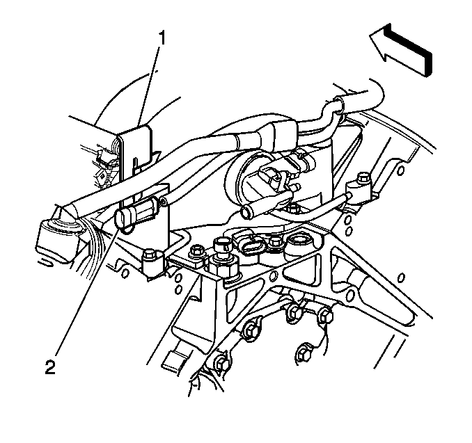
- Remove the knock sensor jumper pigtail (5) from the fuel rail stop bracket (1).
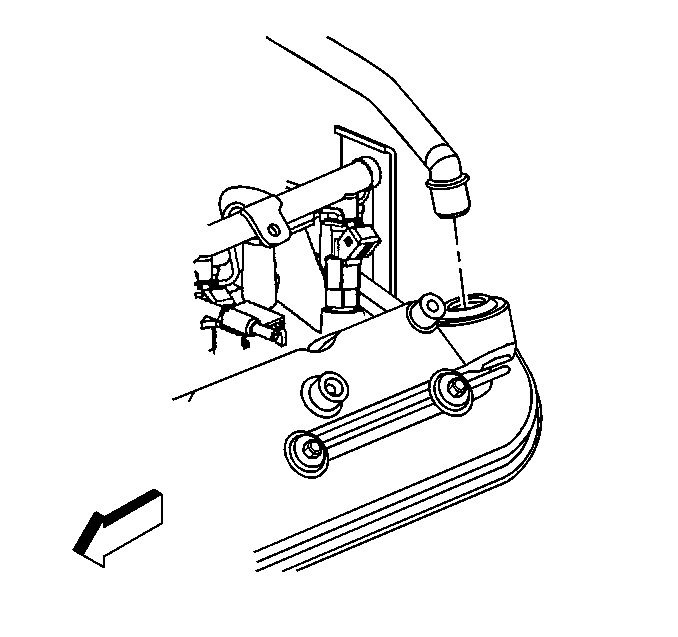
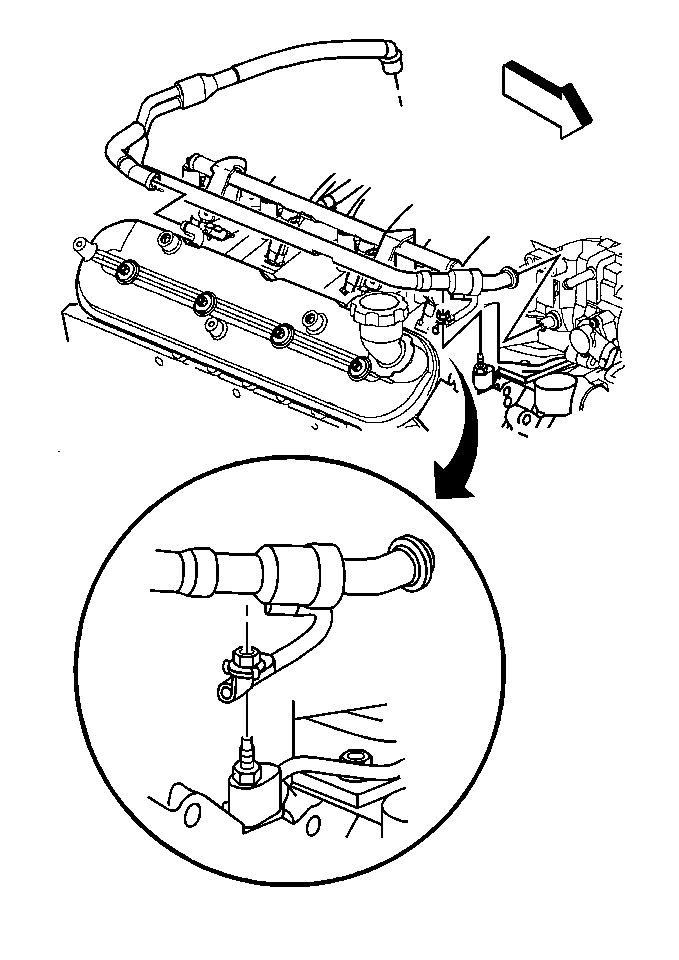
- Remove the positive crankcase ventilation (PCV) valve pipe from the left hand valve rocker arm cover.
- Remove the PCV valve pipe strap nut.
- Remove the PCV valve pipe from the right hand valve rocker arm cover.
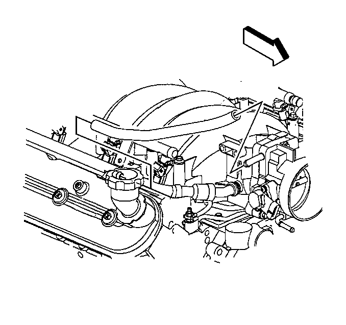
- Remove the PCV tube from the throttle body and the right hand valve rocker arm cover.
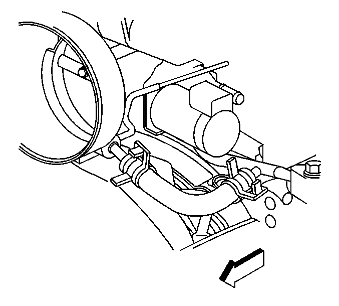
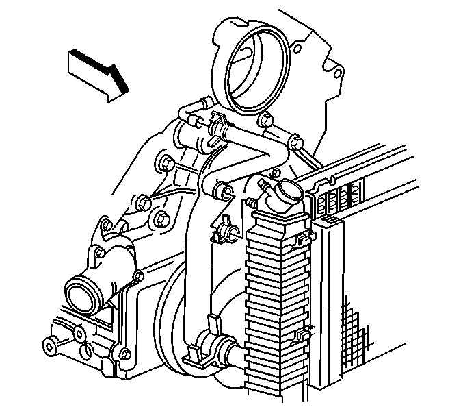
- Remove the engine coolant air bleed hose from the throttle body.
- Remove the throttle body heater outlet hose from the throttle body.
- Remove the intake manifold. Refer to Intake Manifold Removal .
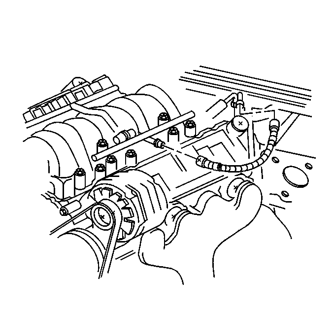
Important: Cap the fittings and plug the holes when separating the fuel system components. This prevents the dripping of fuel and eliminates dirt and other contaminants from entering the fuel system.
Installation Procedure
- Install the intake manifold. Refer to Intake Manifold Installation .
- Install the throttle body heater outlet hose to the throttle body.
- Install the engine coolant air bleed hose to the throttle body.
- Install the PCV tube to the throttle body and right hand valve rocker arm cover.
- Connect the PCV valve pipe to the right hand valve rocker arm cover.
- Install the PCV pipe strap nut.
- Install the PCV valve pipe to the left hand valve rocker arm cover.
- Connect the knock sensor jumper wire pigtail (2) to the fuel rail stop bracket (1).
- Connect the knock sensor electrical connector (4).
- Connect the fuel injector wire harness connectors.
- Connect the throttle position sensor connector.
- Connect all remaining electrical connections to the intake manifold.
- Install the fuel line to the fuel rail.
- Install the fuel rail covers.
- Install the air intake duct and air cleaner assembly.
- Connect the intake air temperature (IAT) sensor connectors at both the air intake duct and the throttle body.
- Connect the mass air flow (MAF) sensor connector at both the air intake duct and the throttle body.


Notice: Use the correct fastener in the correct location. Replacement fasteners must be the correct part number for that application. Fasteners requiring replacement or fasteners requiring the use of thread locking compound or sealant are identified in the service procedure. Do not use paints, lubricants, or corrosion inhibitors on fasteners or fastener joint surfaces unless specified. These coatings affect fastener torque and joint clamping force and may damage the fastener. Use the correct tightening sequence and specifications when installing fasteners in order to avoid damage to parts and systems.
Tighten
Tighten the PCV pipe strap nut to 12 N·m (106 lb in).


