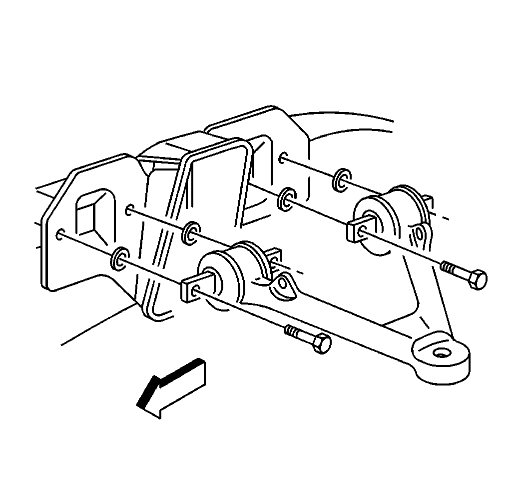
Front Caster Adjustment Procedure
- Loosen the lower control arm cam bolt nuts.
- Rotate the cam bolts to the required caster specification setting. Refer to Wheel Alignment Specifications .
- Maintain the caster setting while tightening the cam bolt nuts.
- Check the caster and camber settings after tightening.
- Adjust the caster and camber setting if necessary.

Notice: Use the correct fastener in the correct location. Replacement fasteners must be the correct part number for that application. Fasteners requiring replacement or fasteners requiring the use of thread locking compound or sealant are identified in the service procedure. Do not use paints, lubricants, or corrosion inhibitors on fasteners or fastener joint surfaces unless specified. These coatings affect fastener torque and joint clamping force and may damage the fastener. Use the correct tightening sequence and specifications when installing fasteners in order to avoid damage to parts and systems.
Tighten
Tighten the front lower control arm cam bolt nuts to 170 N·m
(125 lb ft).
Important: Check the toe setting AFTER changing camber or caster.
Front Camber Adjustment Procedure
- Loosen the lower control arm cam bolt nuts.
- Rotate the cam bolts to the required camber specification setting. Refer to Wheel Alignment Specifications .
- Maintain the camber setting while tightening the cam bolt nuts.
- Check the caster and camber settings after tightening.
- Adjust the caster and camber setting if necessary.
- To obtain additional negative camber beyond cam adjustment capability, remove the washers from the front and rear upper control arm legs.

Notice: Use the correct fastener in the correct location. Replacement fasteners must be the correct part number for that application. Fasteners requiring replacement or fasteners requiring the use of thread locking compound or sealant are identified in the service procedure. Do not use paints, lubricants, or corrosion inhibitors on fasteners or fastener joint surfaces unless specified. These coatings affect fastener torque and joint clamping force and may damage the fastener. Use the correct tightening sequence and specifications when installing fasteners in order to avoid damage to parts and systems.
Tighten
Tighten the front lower control arm cam bolt nuts to 170 N·m
(125 lb ft).
Important: Check toe AFTER changing camber or caster.

Important: The upper control arm shims will have an effect on the camber and the caster. Adding or subtracting shims will change the negative and positive camber and caster settings. Make sure to use an equal thickness of shims on both sides of each individual upper control arm leg.
Check the clearance between the upper control arm and the shock absorber in full rebound, if the shims are removed from the upper control arm.
