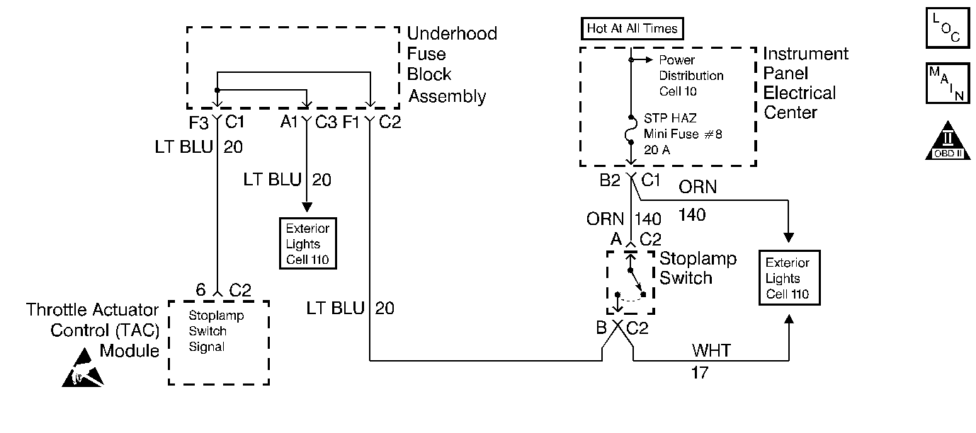
Circuit Description
The Brake Lamp Switch is a normally open switch. When the Brake Lamp Switch is closed, the TAC module senses ignition voltage on the Brake Lamp Switch signal circuit.
If the TAC module senses a voltage on the Brake Lamp Switch signal circuit when the Brake Lamp Switch should be open, this DTC sets.
Conditions for Running the DTC
| • | The engine speed is greater than 700 RPM. |
| • | The wheel speed must be greater than 30 MPH in order to enable the diagnostic. The diagnostic will disable when the wheel speed is below 10 MPH. |
| • | The vehicle speed is decreasing at a rate greater than 10.4 MPH over a one second period. |
Conditions for Setting the DTC
| • | The TAC does not detect voltage on the Brake Lamp Switch circuit when the Brake Lamp Switch should be closed. |
| • | The above conditions present for 1.5 seconds. |
Action Taken When the DTC Sets
| • | The powertrain control module (PCM) stores the DTC information into memory when the diagnostic runs and fails. |
| • | The malfunction indicator lamp (MIL) will not illuminate. |
| • | The PCM records the operating conditions at the time the diagnostic fails. The PCM stores this information in the Failure Records. |
Conditions for Clearing the MIL/DTC
| • | A last test failed, or the current DTC, clears when the diagnostic runs and does not fail. |
| • | A history DTC clears after 40 consecutive warm-up cycles, if failures are not reported by this or any other emission related diagnostic. |
| • | Use a scan tool in order to clear the MIL/DTC. |
Diagnostic Aids
Important:
• Remove any debris from the PCM\TAC module connector surfaces before
servicing the PCM\TAC module. Inspect the PCM\TAC module connector gaskets
when diagnosing/replacing the modules. Ensure that the gaskets are
installed correctly. The gaskets prevent contaminate intrusion into
the PCM\TAC modules. • For any test that requires probing the PCM or a component
harness connector, use the Connector Test Adapter Kit J 35616
. Using this kit prevents damage
to the harness/component terminals. Refer to
Using Connector Test Adapters
in Wiring Systems.
- Test drive the vehicle if you cannot find a problem with the switch or the circuit. An intermittent condition may be duplicated on a test drive.
- For Brake Lamp Switch adjustment, refer to Stop Lamp Switch Adjustment in Hydraulic Brakes.
- For an intermittent condition, refer to Symptoms .
Test Description
The numbers below refer to the step numbers on the diagnostic table.
-
This step determines if the fault is present.
-
This step verifies that the B+ feed is present at the Stop Lamp switch.
-
Test for a short to ground between the fuse and the Stop Lamp switch and between the Stop Lamp switch and the TAC module.
Step | Action | Values | Yes | No |
|---|---|---|---|---|
1 | Did you perform the Powertrain On-Board Diagnostic (OBD) System Check? | -- | ||
Does the display indicate Released? | -- | |||
3 | Depress the brake pedal approximately half-way. Does the display indicate Applied? | -- | Go to Diagnostic Aids | |
4 | Inspect the condition of the Stop Lamp fuse. Is the fuse open? | -- | ||
Is the test lamp illuminated? | -- | |||
6 |
Does the scan tool display Applied? | -- | ||
7 |
Does the display indicate Released? | -- | ||
8 | Inspect the adjustment of the Stop Lamp switch. Refer to Diagnostic Aids. Was an adjustment necessary? | -- | ||
9 |
Did you find and correct the condition? | -- | ||
10 |
Did you find and correct the condition? | -- | ||
Repair the short to ground in the Stop Lamp circuit. Refer to Wiring Repairs in Wiring Systems. Is the action complete? | -- | -- | ||
12 | Repair the open between the Stop Lamp fuse and the Stop Lamp switch. Refer to Wiring Repairs in Wiring Systems. Is the action complete? | -- | -- | |
13 | Replace the Stop Lamp switch. Refer to Stop Lamp Switch Replacement in Hydraulic Brakes. Is the action complete? | -- | -- | |
14 | Replace the TAC module. Refer to Electronic Throttle Actuator Control Module Replacement . Is the action complete? | -- | -- | |
15 |
Does the scan tool indicate that this test ran and passed? | -- | ||
16 | Select the Capture Info option and the Review Info option using the scan tool. Are any DTCs displayed that you have not diagnosed? | -- | Go to applicable DTC table | System OK |
