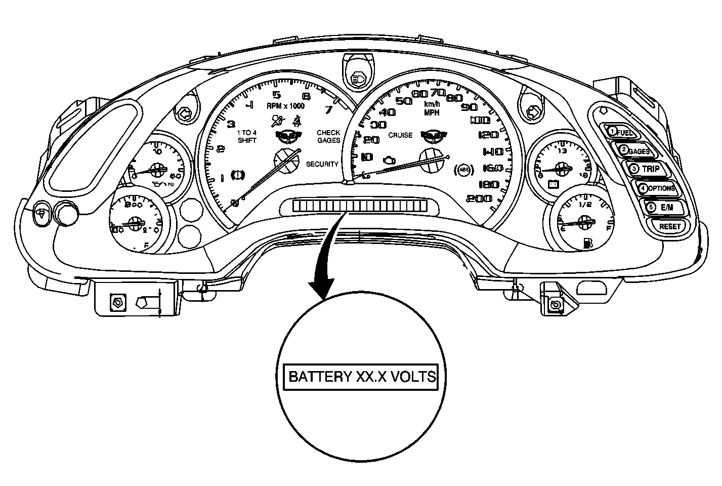
The Instrument Panel Cluster (IPC) serves as the primary
display unit for systems that require display functions. The IPC is capable
of displaying system information and driver warning/status messages
by using three different technologies:
| • | Vacuum Fluorescent (VF) lighting |
Located on the IPC is a 20-character vacuum florescent display
referred to as the Driver Information Center (DIC). The DIC is used to display
driver selectable information and warning/status messages. The
DIC switches are located on the IPC and can be used to access
any of the modes listed. For example, oil pressure can be displayed
by pressing the GAGE button, and personalized option can be
displayed by pressing the OPTIONS button. The following information
can be assessed through the IPC display by selecting the following
DIC switches:
| - | Transmission temperature (Auto trans only) |
| - | Universal Theft Deterrent (UTD) functions |
| - | Lock functions (passive and auto) |
| - | Blank display (fob and tire training mode) |
| - | Used to Acknowledge IPC Messages |
| - | Reset Trip Odometer Functions |
| - | Start/Stop Elapsed Time |
| - | Reset Oil Life Monitor System |
| - | Reset Fuel Economy Functions |
| - | Customize Vehicle Electrical Functions |
| - | Remote Function Actuation (RFA) programming |
| - | Change personalized options |
The IPC is also responsible for indicator illumination and chime functions.
Some indicators are directly controlled by the IPC and others are controlled
by a dedicated circuit to the IPC. The IPC controlled indicators
are illuminated when a message is received on the serial data
line to perform this function. Indicators that are illuminated
by a dedicated wire to the IPC are controlled directly by
other systems which provide all control functions. The IPC controls
all chime functions and is able to determine what indicator is
associated with a chime. The chime is integrated within the
IPC and is not serviced separately.
Instrument Panel Cluster

IPC System Functions
The Instrument Panel Cluster (IPC) is capable of preforming the following
functions:
| • | Ambient light sensor processing |
| • | Oil temperature processing |
| • | Warning/Status message display |
| • | Driver Information Center (DIC) functions |
Wake-Up/Asleep States
Wake-Ups are signals that will turn the IPC ON and cause it to begin
active control and/or monitoring. The IPC is asleep when it has stopped control
or monitoring and has become idle again. The IPC has the ability
to detect wake-up inputs when in the sleep state. Wake-ups
input monitoring is needed to allow the IPC determine when
to wake-up and begin active monitoring and control of vehicle
functions. The IPC will enter a wake-up state under any of
the following conditions:
| • | Any activity on the serial data line |
| • | Power mode message received from the Body Control Module (BCM) |
| • | Battery was disconnected then reconnected |
The IPC has a low power or sleep state. This state is intended to reduce
parasitic load during a period when no control functions are needed. The
IPC will enter a sleep state when all the following conditions
are met:
| • | No Activity on the serial data line for approximately 10 seconds. |
| • | Ignition switch is in the OFF position |
| • | Power mode message was not received from the BCM |
| • | SECURITY indicator is OFF |
If all these conditions are met the IPC will enter a low power or sleep
condition. However, the IPC will still be able to monitor wake-up inputs
and as well as any activity on the serial data line to determine
when to enter a wake-up state.

