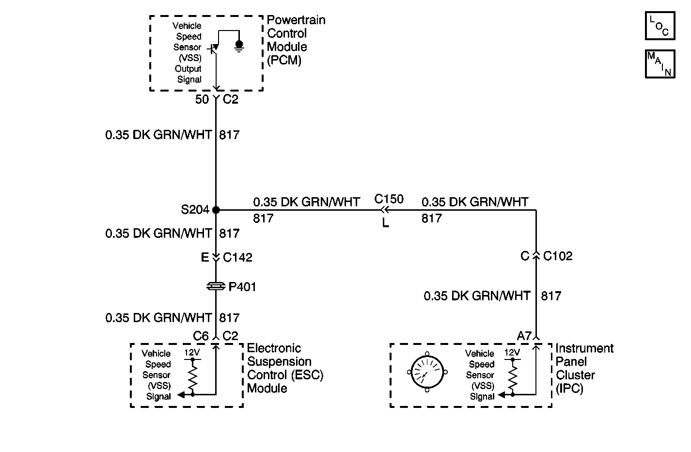
Circuit Description
The Instrument Panel Cluster (IPC) receives vehicle speed information from the Powertrain Control Module (PCM). The IPC receives a 4000 pulse-per mile Vehicle Speed Sensor (VSS) input over a dedicated input from the PCM. The PCM is responsible for processing the VSS data and sending it to the IPC. The IPC will only display the calculated VSS data that was sent from the PCM. The IPC monitors the VSS output information sent from the PCM for an out of range condition.
Conditions for Setting the DTC
| • | The IPC detects vehicle speed information sent from the PCM over 322 km/h (200 mph) on the vehicle speed sensor signal circuit. |
| • | Condition must be present for 1 second. |
Action Taken When the DTC Sets
| • | Stores a DTC B0516 in the IPC memory. |
| • | The IPC will display vehicle speed at 322 km/h (200 mph). |
| • | No driver warning message will be displayed for this DTC. |
Conditions for Clearing the DTC
| • | The IPC detects vehicle speed information sent from the PCM less than 322 km/h (200 mph) on the vehicle speed sensor signal circuit. |
| • | A history DTC will clear after 50 consecutive ignition cycles if the condition for the malfunction is no longer present. |
| • | Use the IPC clear DTC feature. |
| • | Use a scan tool. |
Diagnostic Aids
| • | The following conditions may cause an intermittent malfunction to occur: |
| - | The PCM is unable to process the correct vehicle speed data sent from the VSS. |
| - | Intermittent or erratic VSS operation. |
| • | Test drive the vehicle and check for proper speedometer operation. If the IPC is unable to display the proper vehicle speed information, use a scan tool to display the PCM VSS data. If the PCM is not receiving the proper information from the VSS circuit, then the PCM and VSS circuit must be diagnosed first before diagnosing a DTC B0516. |
| • | Always check for proper speedometer circuit operation by displaying PCM vehicle speed data and checking for stored VSS DTCs with a scan tool before attempting to diagnose a DTC B0516. |
| • | If the DTC is a history DTC, the problem may be intermittent. Perform the tests shown while moving related wiring and connectors. This can often cause the malfunction to occur. |
Test Description
The number(s) below refer to the step number(s) on the diagnostic table.
-
Tests for any VSS DTCs stored in the PCM. Any VSS DTCs stored in the PCM may cause a DTC B0516 to set in the IPC.
-
Tests the speedometer operation. Speedometer malfunctions must be diagnosed and corrected first.
-
Tests for an open, short to voltage, or short to ground in the speedometer signal circuit.
Step | Action | Value(s) | Yes | No |
|---|---|---|---|---|
1 | Did you perform the IPC Diagnostic System Check? | -- | Go to Step 2 | |
Does the scan tool display DTC P0500 or P0608? | -- | Go to Step 3 | ||
Road test the vehicle and observe for proper speedometer operation. Does the speedometer operate properly? | -- | Go to Step 4 | ||
Test the VSS circuit for an open, short to voltage, or short to ground. Refer to Circuit Testing and Wiring Repairs Did you find and correct the condition? | -- | Go to Step 7 | Go to Step 5 | |
5 | Inspect for poor connections at the harness connector of the IPC. Refer to Testing for Intermittent Conditions and Poor Connections and Connector Repairs Did you find and correct the condition? | -- | Go to Step 7 | Go to Step 6 |
6 | Replace the IPC. Refer to Instrument Cluster Replacement . Did you complete the replacement? | -- | Go to Step 7 | -- |
7 |
Does the DTC reset? | -- | Go to Step 6 | System OK |
