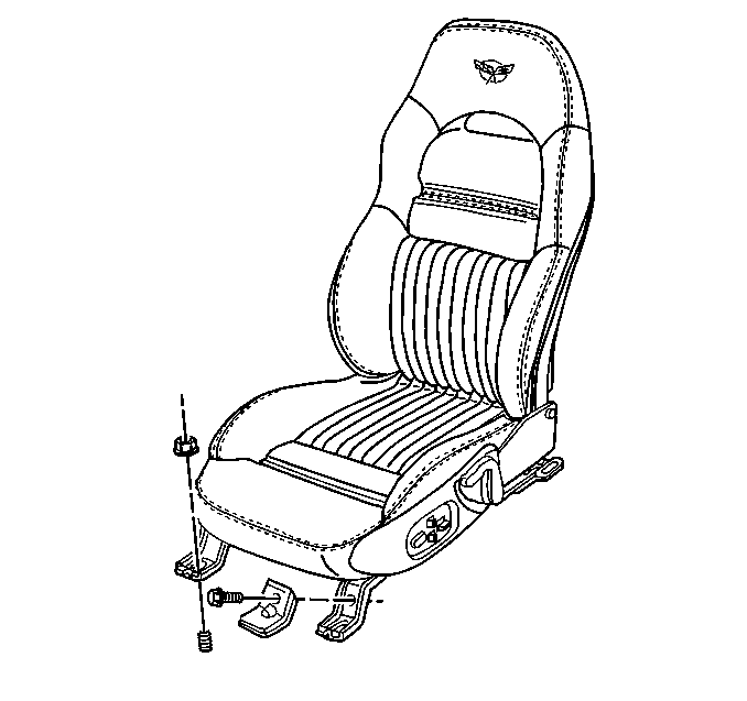
For 1990-2009 cars only
Removal Procedure
The lumbar pump and control module are separate units that are attached to each other by a wire harness and a hose. They are supplied and replaced as an assembly. The lumbar pump is contained in a vinyl pouch under the seat and is tie strapped to the seat adjuster torque tube. The attached control module is contained in a vinyl pouch and is secured with J strips to the bottom of the seat support springs. The service part is supplied with connector fittings and the air hoses are labeled #3, #4, and #5 to aid in assembly.
- Raise the seat to the full up position.
- Remove the seat. Refer to Seat Replacement (Power) .
- Remove the seat cushion cover. Refer to Seat Cushion Trim Cover and Pad Replacement .
- Remove the tie straps attaching the pump to the torque tube (4) under the seat.
- Remove the control module by unhooking the J strips from the seat cushion support wires.
- Disconnect the electrical connector.
- Reposition the pump and the lumbar control module from under the seat support wires to on top of the seat support wires.
- Cut the control module to bladder air hoses (1) 75 mm (3 in) from the control module (5).
- Remove the pump (4) and the control module (5) as an assembly.
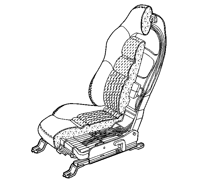
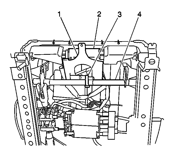
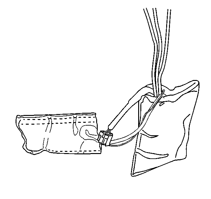
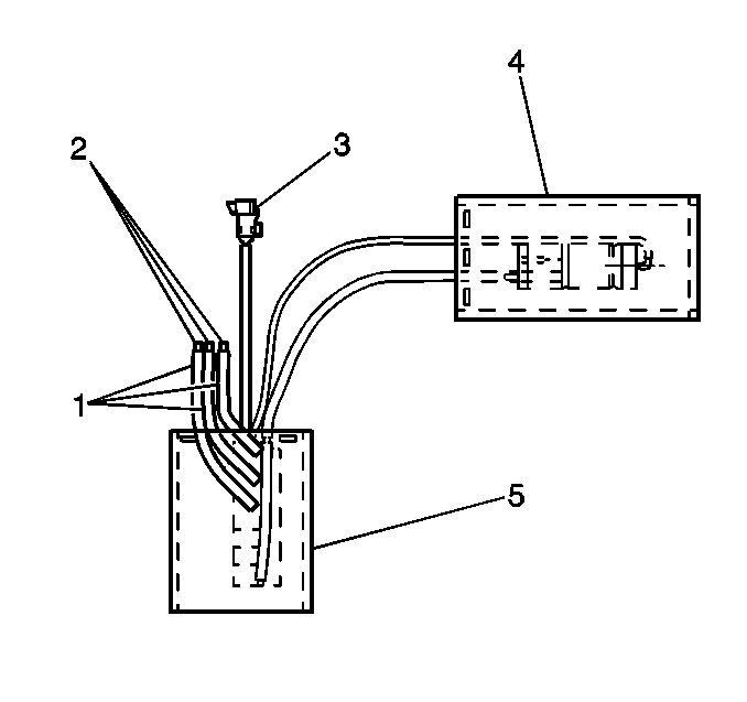
Installation Procedure
- Lay the new pump and control module assembly on top of the seat spring assembly.
- Apply a very small amount of air (blow into the hose) to each of the three lumbar bladder hoses that were cut in step 8.
- Using Loctite™ 406, or equivalent, glue each hose to the fitting (2) in the module hose.
- Insert the pump and the control module down under the seat support wires.
- Attach the control module with the J strips facing outward to the underside of the seat cushion support wires.
- Connect the electrical connector to the control module.
- Tie strap the pump to the torque tube (4) under the front of the seat.
- Install the seat cushion trim cover. Refer to Seat Cushion Trim Cover and Pad Replacement .
- Install the seat. Refer to Seat Replacement (Power) .

| • | If the upper lumbar inflates, use the procedure in step three to connect that hose to the hose labeled #3 on the new pump. |
| • | If the lower lumbar inflates, use the procedure in step three to connect that hose to the hose labeled #4 on the new pump. |
| • | If the bolsters inflate, use the procedure in step three to connect that hose to the hose labeled #5 on the new pump. |

| 3.1. | Position the hose so it is just over the edge of the barb on the attaching fitting. |
| 3.2. | Apply the adhesive completely around the fitting. |
| 3.3. | Quickly push the hose the rest of the way onto the fitting. |

