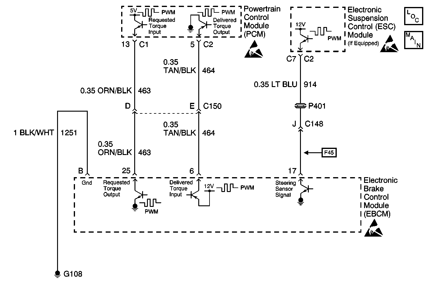
Circuit Description
The PCM monitors various parameters and will not allow Traction Control/Active Handling (if equipped with RPO JL4) operation if any parameter falls beyond a predetermined value.
Conditions for Setting the DTC
A malfunction has been detected by the PCM. The PCM then causes TCS/Active Handling shutdown until the malfunction has been corrected.
Action Taken When the DTC Sets
This is a temporary operational malfunction.
TCS/Active Handling (if equipped with RPO JL4) are disabled.
| • | Indicators that turn on: |
| Car Icon (TCS indicator) |
| • | Messages displayed on the DIC: |
| Service Traction System |
| Service Active HNDLG (if equipped with RPO JL4) |
Conditions for Clearing the DTC
| • | Condition for DTC is no longer present and scan tool clear DTC function is used. |
| • | Fifty ignition cycles have passed with no DTCs detected. |
Diagnostic Aids
This code is for information only. It indicates there are no problems in the ABS/TCS/Active Handling system, is used as an aid to the technician.
Test Description
The numbers below refer to step numbers on the diagnostic table.
Step | Action | Value(s) | Yes | No |
|---|---|---|---|---|
1 | Was the Diagnostic System Check performed? | -- | ||
2 | Check the following grounds, G101 and G108 making sure each ground is clean tight and free of damage. Refer to Ground Distribution Schematics in Wiring Systems. Were any loose, damaged, or corroded grounds found? | -- | ||
3 | Repair ground as necessary. Refer to Wiring Repairs in Wiring Systems. Is the repair complete? | -- | -- | |
Is the duty cycle within the range specified in the value(s) column? | 85-95 % | |||
Using J 39200 DMM, measure the AC Hz between J 39700 terminals 25 and B. Is the frequency within the range specified in the value(s) column? | 121-134 Hz | |||
6 |
Is the voltage within the range specified in the value(s) column? | 4.5-5.5 V | ||
7 | Replace the EBCM. Refer to Electronic Brake Control Module Replacement. Is the replacement complete? | -- | -- | |
8 |
Is the voltage greater then the value specified in the value(s) column? | 1 V | ||
9 | Repair CKT 463 for a short to voltage. Refer to Wiring Repairs in Wiring Systems. Is the repair complete? | -- | -- | |
10 |
Is the resistance within the range specified in the value(s) column? | OL (infinite) | ||
11 | Repair CKT 463 for a short to ground. Refer to Wiring Repairs in Wiring Systems. Is the repair complete? | -- | -- | |
12 | Using J 39200 DMM, measure the resistance between terminal 25 of J 39700 and the PCM connector C1 terminal 13. Is the resistance within the range specified in the value(s) column? | 0-2 Ω | ||
13 | Replace the PCM. Refer to PCM/TAC Module Replacement in Engine Controls. Is the diagnosis complete? | -- | -- | |
14 | Repair CKT 463 for an open. Refer to Wiring Repairs in Wiring Systems. Is the repair complete? | -- | -- |
