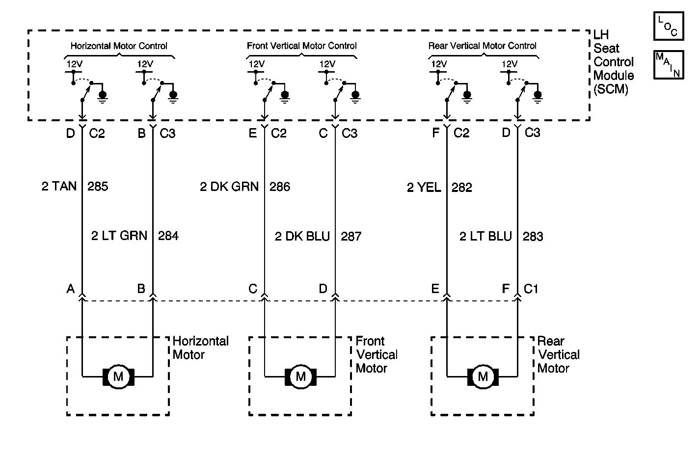
Circuit Description
The LH Seat Control Module (SCM) controls the output functions of the LH seat motors after it receives a valid seat switch input. The LH seat switch provides the input to the SCM whenever a request is made. The SCM will provide either voltage or ground to the relative seat motor circuit depending on the desired seat position. The SCM monitors the seat motor control circuits for the possibility of a short to battery voltage. If at anytime the SCM senses voltage on CKT's 282, 283, 284, 285, 286 or 287 when a seat request has not been made, the SCM will disable the seat motor and set a DTC.
Conditions for Setting the DTC
| • | The SCM detects voltage present in the rear vertical, front vertical, or horizontal seat motor control circuits during an idle state. |
| • | Condition must be present for 2 seconds. |
Action Taken When the DTC Sets
| • | Stores a history DTC B2600 in the SCM memory. |
| • | This DTC can only be set as a history code even if the malfunction is current. |
| • | No driver warning message will be displayed for this DTC. |
| • | The operation/function of the faulted motor is disabled until the fault is corrected. |
Conditions for Clearing the DTC
| • | The SCM no longer detects a short to battery voltage condition in the seat motor control circuits for longer than 2 seconds. |
| • | Use the IPC clearing DTCs feature. |
| • | Using a scan tool. |
Diagnostic Aids
| • | If the DTC does not reset after the code is cleared, then the problem may be intermittent. Perform the tests shown while moving related wiring and connectors. This can often cause the malfunction to occur. Refer to Testing for Intermittent Conditions and Poor Connections in Wiring Systems. |
| • | If the rear vertical seat motor circuit is shorted to battery voltage, the seat will operate only in certain directions depending on what circuit was affected. |
| • | Using a scan tool, select SCM inputs and monitor the seat motor voltages while operating the seat motors in different directions. If the scan tool displays abnormal seat motor voltage, check the seat motor circuit for a short. |
Step | Action | Value(s) | Yes | No | ||||||||||||
|---|---|---|---|---|---|---|---|---|---|---|---|---|---|---|---|---|
1 | Were you sent here from the Power Seat Diagnostic System Check? | -- | ||||||||||||||
2 |
Does the DMM display any voltage on any of the seat motor control circuits during the above test? | -- | ||||||||||||||
3 | Repeat the test above in step 2, however this time perform it with the LH seat control module (SCM) connectors C2 and C3 disconnected. Does the DMM display any voltage on any of the seat motor control circuits during the above test? | -- | ||||||||||||||
4 | Repair a short to battery voltage relative to the circuit being tested in steps 2 and 3.
Is the repair complete? | -- | -- | |||||||||||||
5 | Replace the LH seat control module (SCM). Refer to Memory Seat Control Module Replacement . Is the repair complete? | -- | -- | |||||||||||||
6 |
Did you correct the condition? | -- | System OK |
