Telescope Actuator Assembly - Assemble - Off Vehicle Telescoping Column
Tools Required
J 41352 Steering
Column Holding Fixture

Notice: Use the correct fastener in the correct location. Replacement fasteners
must be the correct part number for that application. Fasteners requiring
replacement or fasteners requiring the use of thread locking compound or sealant
are identified in the service procedure. Do not use paints, lubricants, or
corrosion inhibitors on fasteners or fastener joint surfaces unless specified.
These coatings affect fastener torque and joint clamping force and may damage
the fastener. Use the correct tightening sequence and specifications when
installing fasteners in order to avoid damage to parts and systems.
- Perform the following to install the telescope adapter assembly:
| 1.1. | Install the telescope adapter assembly (2) to the telebearing
and jacket assembly. |
| 1.2. | Install the 3 flat head 6-lobed soc tap screws (1). |
Tighten
Tighten the screws to 9 N·m (80 lb in).

- To install the telescope
actuator assembly (3), follow these steps:
| 2.1. | Install the telescope actuator assembly (3) to the telebearing
jacket assembly. |
| 2.2. | Install the 4 TORX® head screws (4). |
Tighten
Tighten the screws to 9 N·m (80 lb in).
| 2.3. | Install the telescope drive ball (2). |
| 2.4. | Lubricate the telescope drive bolt (1). |
| 2.5. | Install the telescope drive bolt (1). |
Tighten
Tighten the bolt to 7 N·m (62 lb in).

Caution: Improper routing of the wire harness assembly may damage the inflatable
restraint steering wheel module coil. This may result in a malfunction of
the coil, which may cause personal injury.
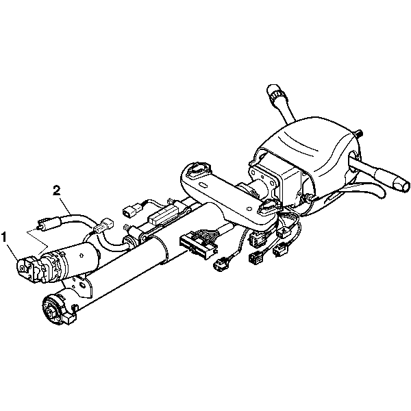
- Connect the cable assembly (2) to the telescope
drive motor assembly (1).

- Install the following
items onto the telebearing and jacket assembly:
| 4.1. | Install the anti rotation ball (4). |
| 4.2. | Lubricate the shoulder bolt (3). |
| 4.3. | Install the shoulder bolt (3). |
| 4.4. | Install the compression spring (2). |
| 4.5. | Install the retaining ring (1). |

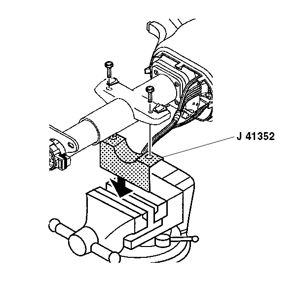
- Remove the steering column
from J 41352
.
- Remove J 41352
from
the vise.
- Enable the inflatable restraint steering wheel module. Refer to
Enabling the SIR System
in SIR.


