Evaporator Tube Replacement Front
Tools Required
J 39400-A Halogen Leak Detector
Removal Procedure
- Recover the refrigerant from the A/C system. Refer to Refrigerant Recovery and Recharging .
- Remove the battery heat shield. Refer to Battery Heat Shield Replacement in Engine Electrical.
- Remove the upper radiator support. Refer to Radiator Support Replacement in Engine Cooling.
- Disconnect the refrigerant pressure sensor electrical connector.
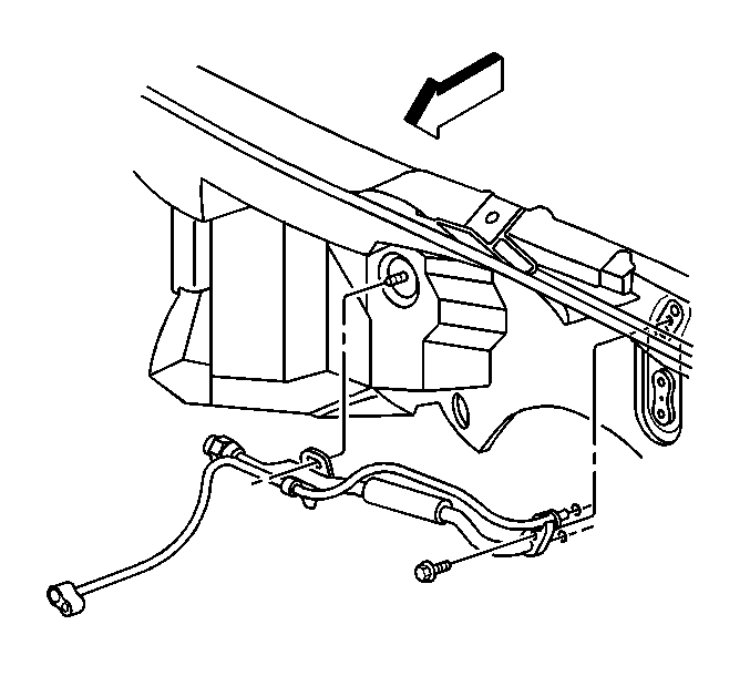
- Remove the front evaporator tube to condenser retaining bolt.
- Disconnect the front evaporator tube from the condenser.
- Remove the front evaporator tube to rear evaporator tube retaining bolt.
- Disconnect the front evaporator tube from the rear evaporator tube.
- Remove the front evaporator tube from the vehicle.
- Remove the A/C refrigerant pressure sensor from the evaporator tube.
- Discard the O-rings.


Important: Cap or tape the open front evaporator tube and the condenser immediately to prevent contamination.

Important: Cap or tape the open evaporator tubes immediately to prevent contamination.


Installation Procedure
- Install the A/C refrigerant pressure sensor to the evaporator tube.
- Remove the cap or tape from the evaporator tubes.
- Using a lint-free clean, dry cloth, carefully clean the sealing surfaces of the front evaporator tube and the rear evaporator tube.
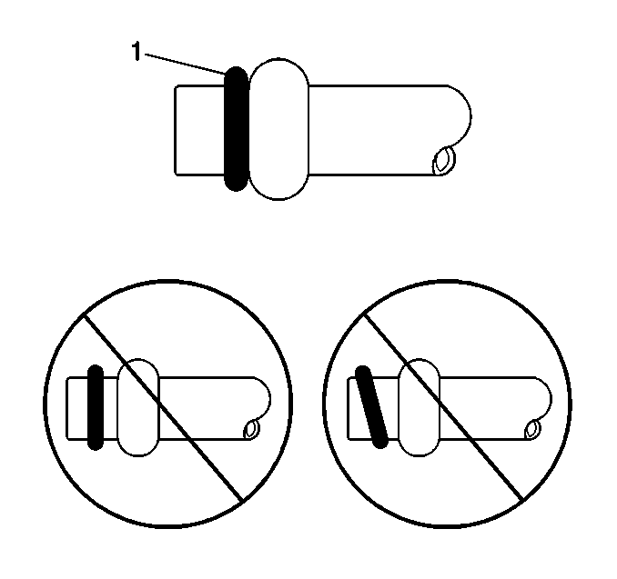
- Lightly coat the new O-ring seal (1) with mineral base 525 viscosity refrigerant oil.
- Carefully slide the new O-ring (1) onto the front evaporator tube until seated.
- Install the front evaporator tube to the vehicle.
- Install the front evaporator tube to the rear evaporator tube.
- Install the front evaporator tube to rear evaporator tube retaining bolt.
- Remove the cap or tape from the front evaporator tube and the condenser.
- Using a lint-free clean, dry cloth, carefully clean the sealing surfaces of the front evaporator tube and the condenser.
- Lightly coat the new O-ring seal (1) with mineral base 525 viscosity refrigerant oil.
- Carefully slide the new O-ring (1) onto the front evaporator tube until seated.
- Install the front evaporator tube to the condenser.
- Install the front evaporator tube to condenser retaining bolt.
- Connect the refrigerant pressure sensor electrical connector.
- Install the upper radiator support. Refer to Radiator Support Replacement in Engine Cooling.
- Evacuate and recharge the A/C system. Refer to Refrigerant Recovery and Recharging .
- Install the battery heat shield. Refer to Battery Heat Shield Replacement in Engine Electrical.
- Leak test the fittings of the component using J 39400-A .
Notice: Use the correct fastener in the correct location. Replacement fasteners must be the correct part number for that application. Fasteners requiring replacement or fasteners requiring the use of thread locking compound or sealant are identified in the service procedure. Do not use paints, lubricants, or corrosion inhibitors on fasteners or fastener joint surfaces unless specified. These coatings affect fastener torque and joint clamping force and may damage the fastener. Use the correct tightening sequence and specifications when installing fasteners in order to avoid damage to parts and systems.

Tighten
Tighten the sensor to 4.75 N·m (42 lb in).
Important: DO NOT allow any of the mineral base 525 viscosity refrigerant oil on the O-ring seal to enter the refrigerant system.
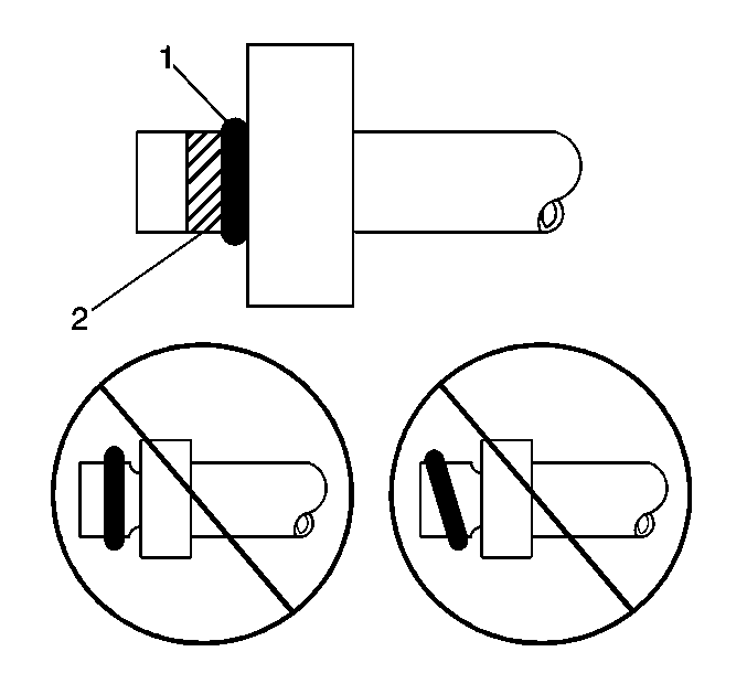
Leave a light coating of the refrigerant oil on the front evaporator tube in the area indicated (2) ONLY.


Tighten
Tighten the bolt to 25 N·m (18 lb ft).

Important: DO NOT allow any of the mineral base 525 viscosity refrigerant oil on the O-ring to enter the refrigerant system.
Leave a light coating of the refrigerant oil on the evaporator tube in the area indicated (2) ONLY.

Tighten
Tighten the bolt to 27 N·m (20 lb ft).

Evaporator Tube Replacement Rear
Tools Required
J 39400-A Halogen Leak Detector
Removal Procedure
- Recover the refrigerant from the A/C system. Refer to Refrigerant Recovery and Recharging .
- Remove the battery. Refer to Battery Replacement in Engine Electrical.
- Remove the battery heat shield. Refer to Battery Heat Shield Replacement in Engine Electrical.
- Remove the intake manifold. Refer to Intake Manifold Replacement in Engine Mechanical.
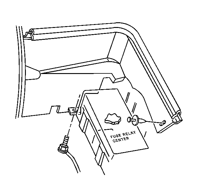
- Remove the nut retaining the heater pipe bracket to the cowl.
- Reposition the heater pipe bracket to access the refrigerant lines.
- Remove the front evaporator tube to rear evaporator tube retaining bolt.
- Disconnect the evaporator tubes, discard the O-ring.
- Loosen the accumulator hose to evaporator retaining bolt.
- Disconnect the rear evaporator tube from the accumulator hose bracket at the evaporator, discard the O-ring.
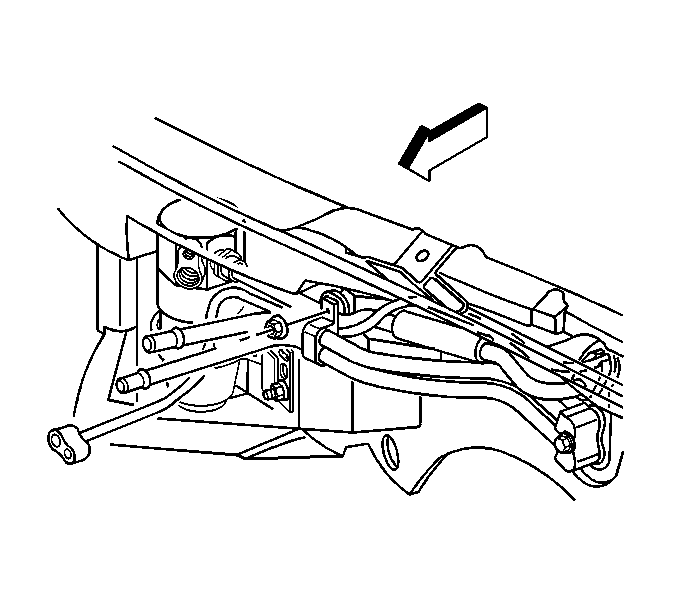

Important: Cap or tape the open evaporator tubes immediately.
Important: Cap or tape the open rear evaporator tube and the evaporator immediately to prevent contamination.
Installation Procedure
- Remove the cap or tape from the rear evaporator tube and evaporator.
- Using a lint-free clean, dry cloth, carefully clean the sealing surfaces of the rear evaporator tube and evaporator.
- Lightly coat the new O-ring (1) with mineral base 525 viscosity refrigerant oil.
- Carefully slide the new O-rings (1) onto the rear evaporator tube and evaporator until seated.
- Position the rear evaporator tube with the accumulator hose bracket and install the assembly to the evaporator.
- Tighten the accumulator hose to evaporator retaining bolt.
- Remove the cap or tape from the front evaporator tube.
- Using a lint-free clean, dry cloth, carefully clean the sealing surfaces of the front evaporator tube where it connects to the rear evaporator tube.
- Lightly coat the O-ring (1) with mineral base 525 viscosity refrigerant oil.
- Carefully slide the new O-ring (1) onto the front evaporator tube until seated.
- Install the front evaporator tube to the rear evaporator tube with retaining bolt.
- Install the heater pipe bracket to the cowl stud.
- Install the heater pipe bracket retaining nut.
- Install the intake manifold. Refer to Intake Manifold Replacement in Engine Mechanical.
- Install the battery heat shield. Refer to Battery Heat Shield Replacement in Engine Electrical.
- Install the battery. Refer to Battery Replacement in Engine Electrical.
- Evacuate and recharge the A/C system. Refer to Refrigerant Recovery and Recharging .
- Leak test the fittings of the component using J 39400-A .

Important: DO NOT allow any of the mineral base 525 viscosity refrigerant oil on the O-ring to enter the refrigerant system.


Notice: Use the correct fastener in the correct location. Replacement fasteners must be the correct part number for that application. Fasteners requiring replacement or fasteners requiring the use of thread locking compound or sealant are identified in the service procedure. Do not use paints, lubricants, or corrosion inhibitors on fasteners or fastener joint surfaces unless specified. These coatings affect fastener torque and joint clamping force and may damage the fastener. Use the correct tightening sequence and specifications when installing fasteners in order to avoid damage to parts and systems.
Tighten
Tighten the bolt to 16 N·m (12 lb ft).
Important: DO NOT allow any of the mineral base 525 viscosity refrigerant oil on the O-ring to enter the refrigerant system.


Leave a light coating of the refrigerant oil on the front evaporator tube in the area indicated (2) ONLY.

Tighten
Tighten the bolt to 25 N·m (18 lb ft).

Tighten
Tighten the nut to 10 N·m (89 lb in).


