Tools Required
J 39400-A Halogen Leak Detector
Removal Procedure
- Recover the refrigerant from the A/C system. Refer to Refrigerant Recovery and Recharging .
- Remove the battery heat shield. Refer to Battery Heat Shield Replacement in Engine Electrical.
- Remove the water pump. Refer to Water Pump Replacement in Engine Cooling.
- Remove the compressor drive belt. Refer to Air Conditioning Compressor Belt Replacement in Engine Mechanical.
- Disconnect the compressor clutch electrical connector.
- Raise and support the vehicle. Refer to Lifting and Jacking the Vehicle in General Information.
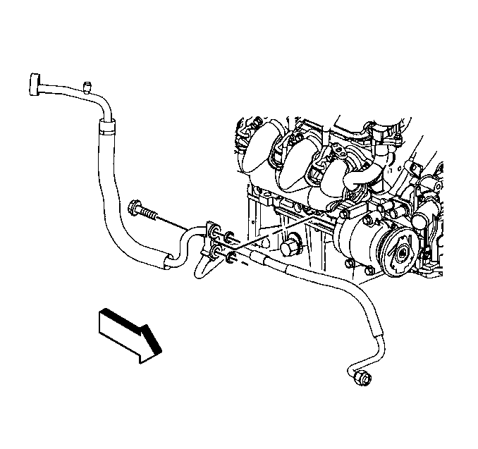
- Remove the compressor hose retaining bolt.
- Disconnect the compressor hose from the compressor, discard the seal washers and cap or tape the hose end to prevent contamination.
- Remove the lower compressor mounting bolts.
- Lower the vehicle.
- Remove the compressor mounting nut.
- Fully loosen the compressor mounting stud.
- Remove the upper compressor mounting bolt.
- Remove the compressor and the mounting stud from the engine block.
- Remove the compressor mounting stud from the compressor.
- If replacing the compressor, drain and measure as much of the oil as possible from the removed compressor:


Important: Cap or tape the open compressor hose immediately to prevent contamination.


| 16.1. | Drain the oil from both the suction and discharge ports of the removed compressor into a clean container. |
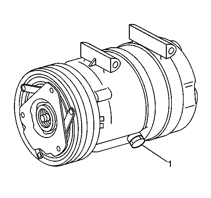
| 16.2. | Remove the compressor crankcase oil drain plug (1) and drain the crankcase oil into the same container. |
| 16.3. | Measure and record the amount of oil drained from the removed compressor. |
This measurement will be used during installation of the replacement compressor.
| 16.4. | Properly discard the used PAG oil. |
Installation Procedure
Important: The replacement compressor is shipped without PAG oil.
Refer to Refrigerant System Capacities for compressor oil capacity.
- Add the proper amount of PAG oil to the compressor crankcase.
- Install the compressor drain plug (1).
- Tighten the compressor drain plug.
- Install the compressor mounting stud to the compressor.
- Install the compressor into position on the compressor mounting bracket.
- Install the compressor mounting stud to the engine block.
- Install the upper compressor mounting bolt.
- Raise and support the vehicle.
- Install the lower compressor mounting bolts.
- Lower the vehicle.
- Tighten the compressor mounting stud.
- Tighten the compressor mounting bolts in the following sequence:
- Raise and support the vehicle.
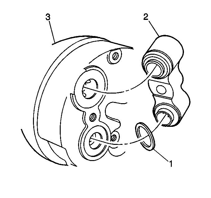
- Remove the cap or tape from the compressor hose end (2).
- Using a lint-free clean, dry cloth, carefully clean the sealing surfaces of the compressor hose (2) and the compressor (3).
- Lightly coat the new sealing washers (1) with mineral base 525 viscosity refrigerant oil.
- Carefully slide the new sealing washers (1) onto the compressor hose (2) until seated.
- Install the compressor hose to the compressor.
- Install the compressor hose to compressor retaining bolt.
- Tighten the compressor hose to compressor retaining bolt.
- Lower the vehicle.
- Connect the compressor clutch electrical connector.
- Install the compressor drive belt. Refer to Air Conditioning Compressor Belt Replacement in Engine Mechanical.
- Install the water pump. Refer to Water Pump Replacement in Engine Cooling.
- Install the battery heat shield. Refer to Battery Heat Shield Replacement in Engine Electrical.
- Refill the cooling system. Refer to Cooling System Draining and Filling in Engine Cooling.
- Evacuate and recharge the A/C system. Refer to Refrigerant Recovery and Recharging .
- Leak test the fittings of the component using J 39400-A .

Notice: Use the correct fastener in the correct location. Replacement fasteners must be the correct part number for that application. Fasteners requiring replacement or fasteners requiring the use of thread locking compound or sealant are identified in the service procedure. Do not use paints, lubricants, or corrosion inhibitors on fasteners or fastener joint surfaces unless specified. These coatings affect fastener torque and joint clamping force and may damage the fastener. Use the correct tightening sequence and specifications when installing fasteners in order to avoid damage to parts and systems.
Tighten
Tighten the drain plug to 20 N·m (15 lb ft).


Tighten
Tighten the stud to 9 N·m (80 lb in).
| 12.1. | Front upper, first |
| 12.2. | Front lower, second |
| 12.3. | Rear lower, third |
Tighten
Tighten the bolts in sequence to 40 N·m (30 lb ft).
| 12.4. | Install the compressor mounting nut. |
Tighten
Tighten the nut to 40 N·m (30 lb ft).

Important: DO NOT allow any of the mineral base 525 viscosity refrigerant oil on the seal washers to enter the refrigerant system.

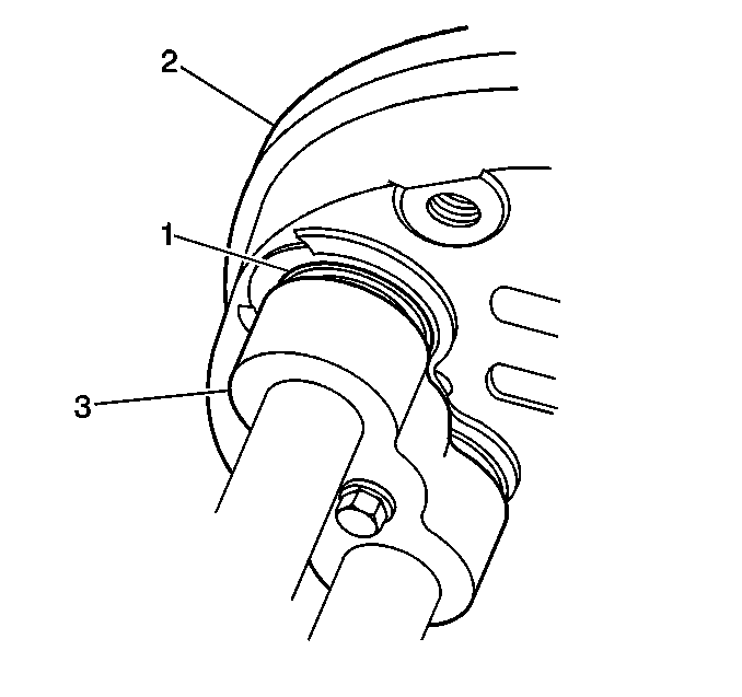
Important: After tightening the compressor hose to the compressor, there should be a slight sealing washer gap of approximately 1.2 mm (3/64 in) between the compressor hose and the compressor.

Tighten
Tighten the bolt to 26 N·m (19 lb ft).

