Front Hinge Pillar Body Replacement Corvette
Removal Procedure
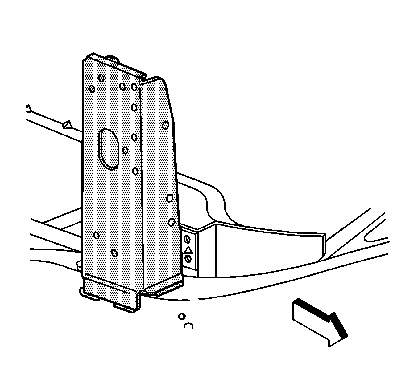
The front hinge pillar panel is bolted, welded and bonded with structural adhesive to the side structure and frame rail. The replacement front hinge pillar panel is serviced as an assembly. You must remove and replace the side door opening panel in order to replace the front hinge pillar.
- Disable the SIR system. Refer to SIR Disabling and Enabling in SIR.
- Disconnect the negative battery cable. Refer to Battery Negative Cable Disconnection and Connection in Engine Electrical.
- Remove all related panels and components.
- Repair as much of the damage as possible to factory specifications. Refer to Dimensions - Body .
- Note the location of the sealers and the anti-corrosion materials and remove these components from the repair area as necessary. Refer to Anti-Corrosion Treatment and Repair in Paint and Coatings.
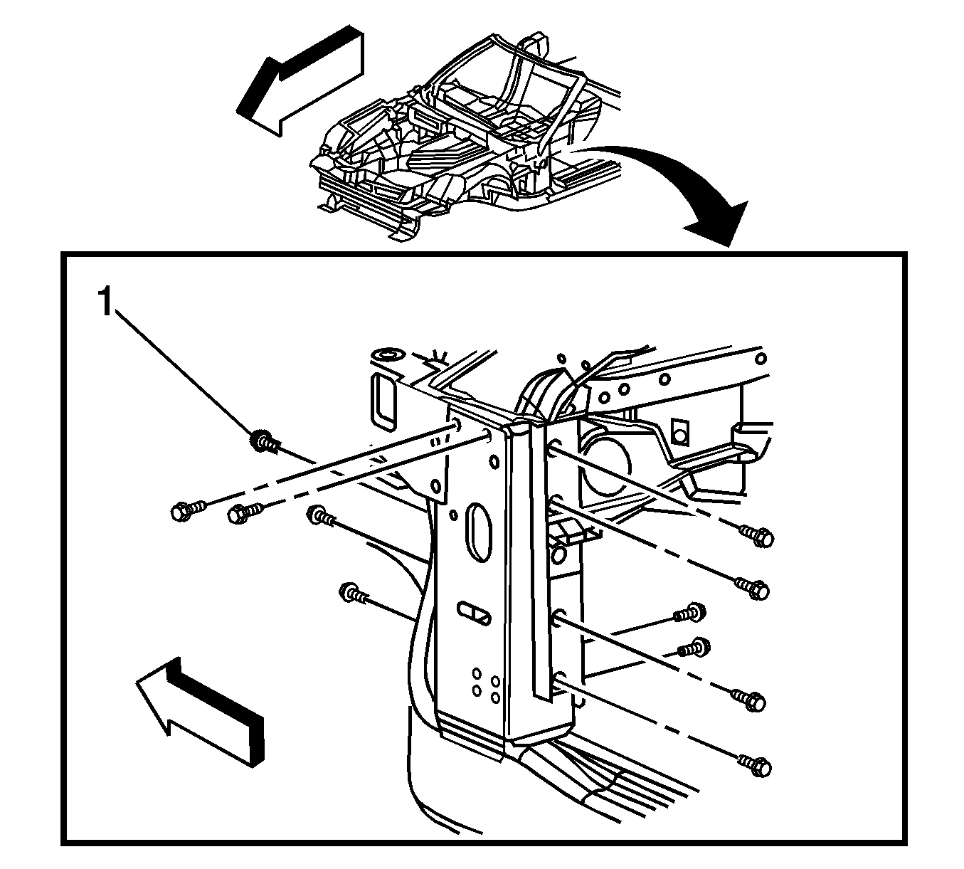
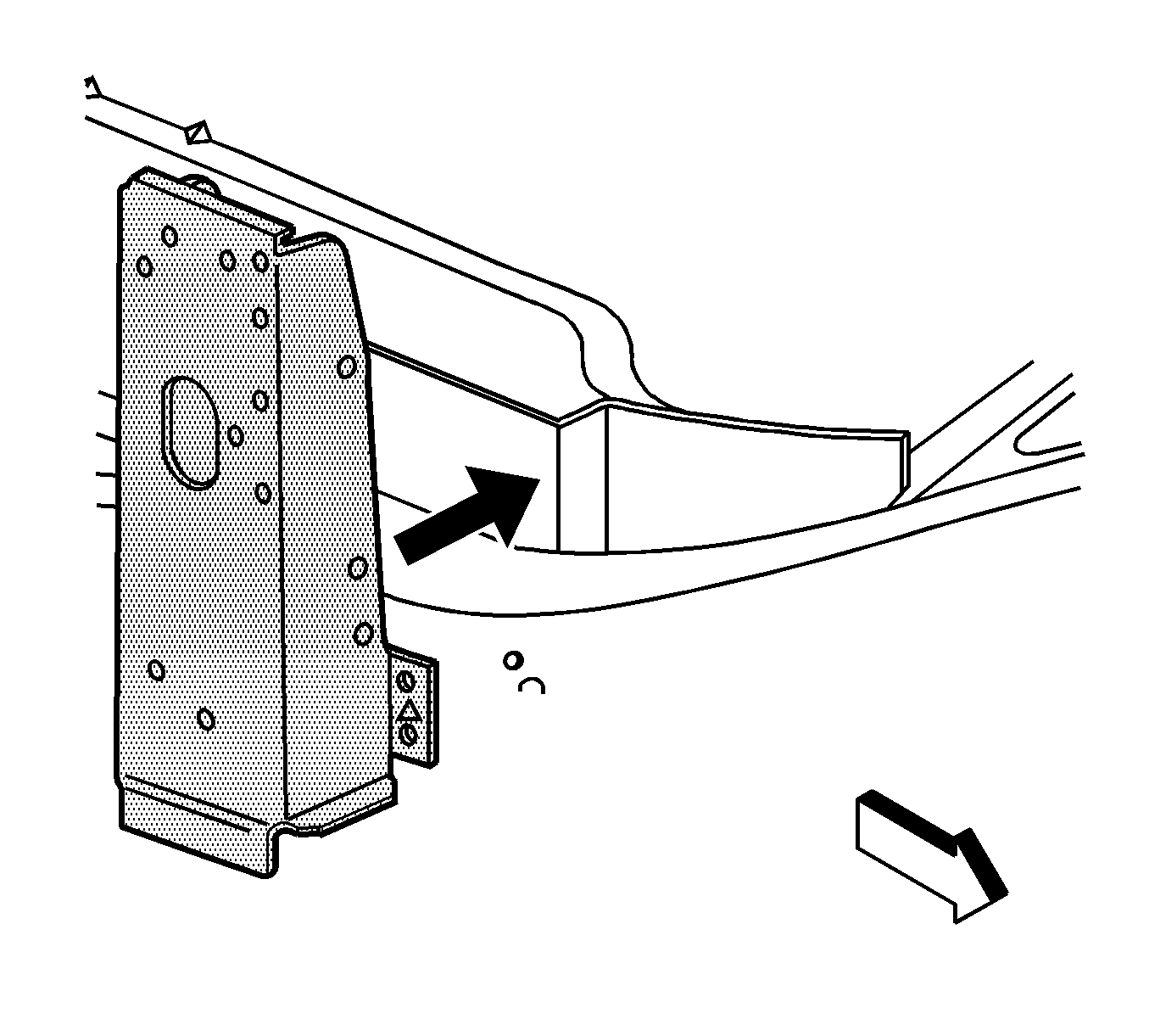
- Remove the bolts (1) attaching the front hinge pillar to the windshield frame.
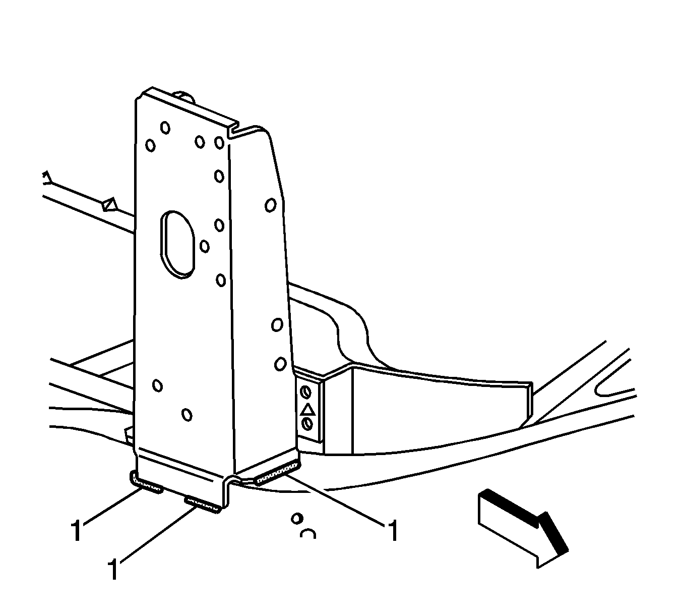
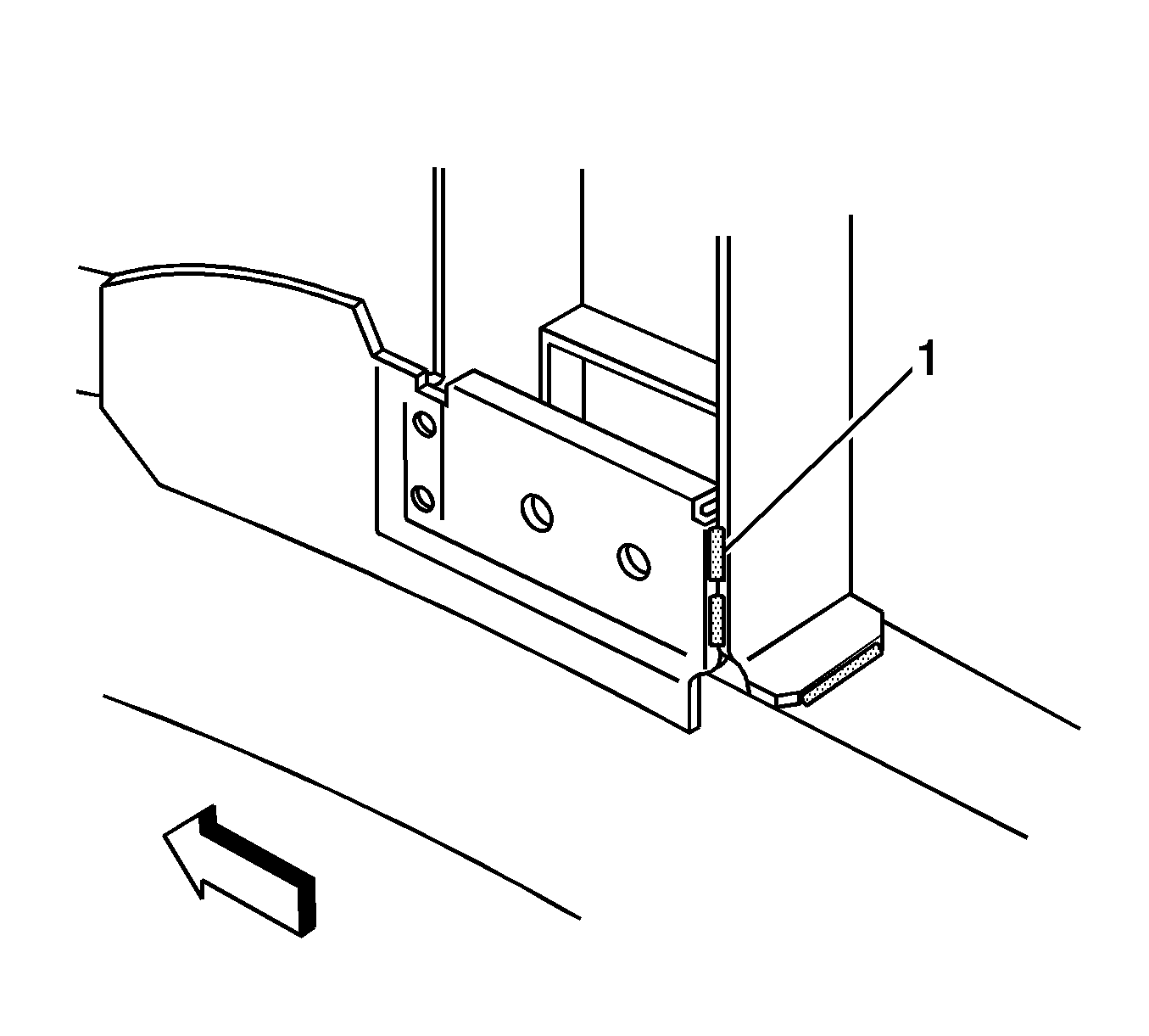
- Locate and remove all factory welds (1) from the outer hinge pillar. Note the number and location of the welds for installation of the new hinge pillar.
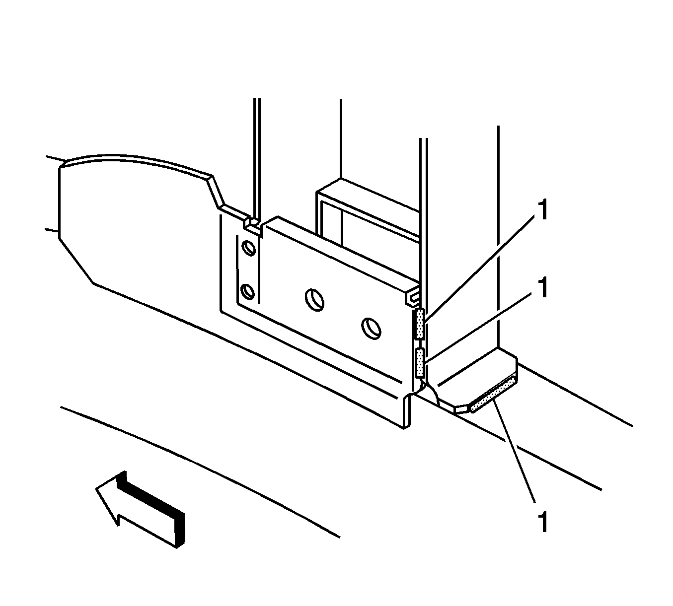
- Locate and remove all factory welds (1) from the inner hinge pillar. Note the number and location of the welds for installation of the new hinge pillar.
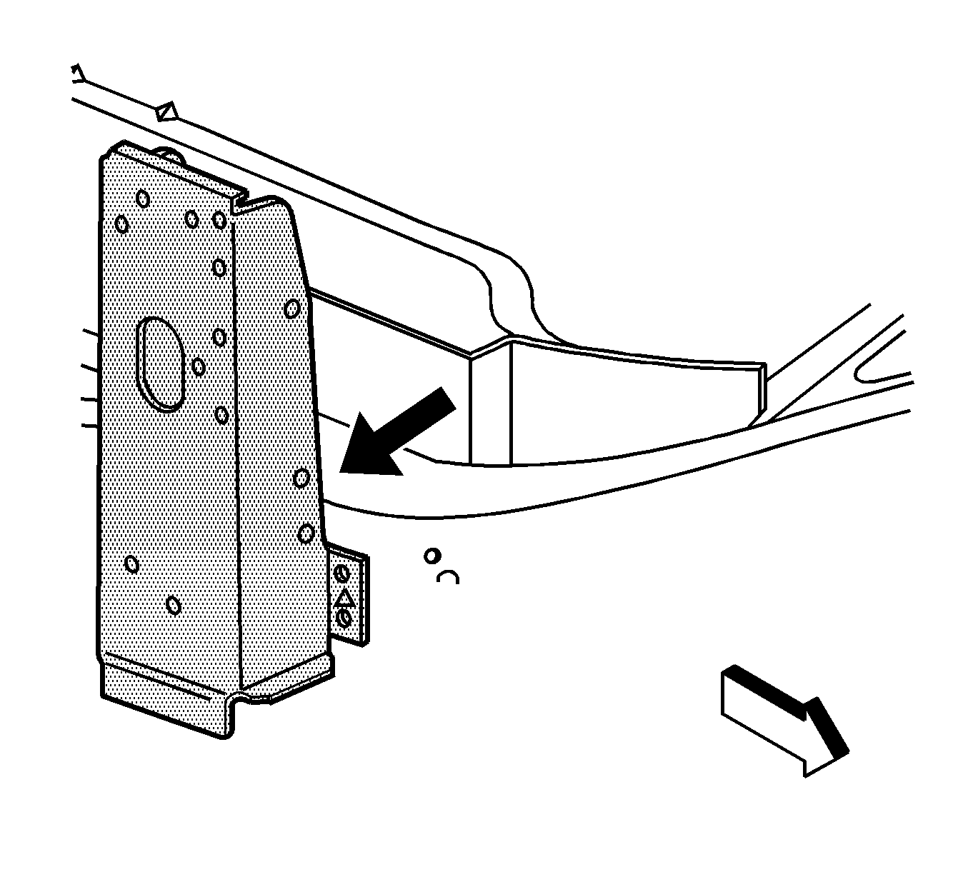
- Remove the damaged hinge pillar.
- Note the location of the adhesive and remove all remaining loose adhesive.
Caution: Refer to Approved Equipment for Collision Repair Caution in the Preface section.
Important: Do NOT damage the inner panels or the reinforcements.
Installation Procedure
- Before applying the adhesive, dry fit the hinge pillar for proper fit and alignment.
- Prepare all welding attachment surfaces as necessary.
- Clean and prepare all bonding mating surfaces according to the adhesive manufacturer's recommendations.
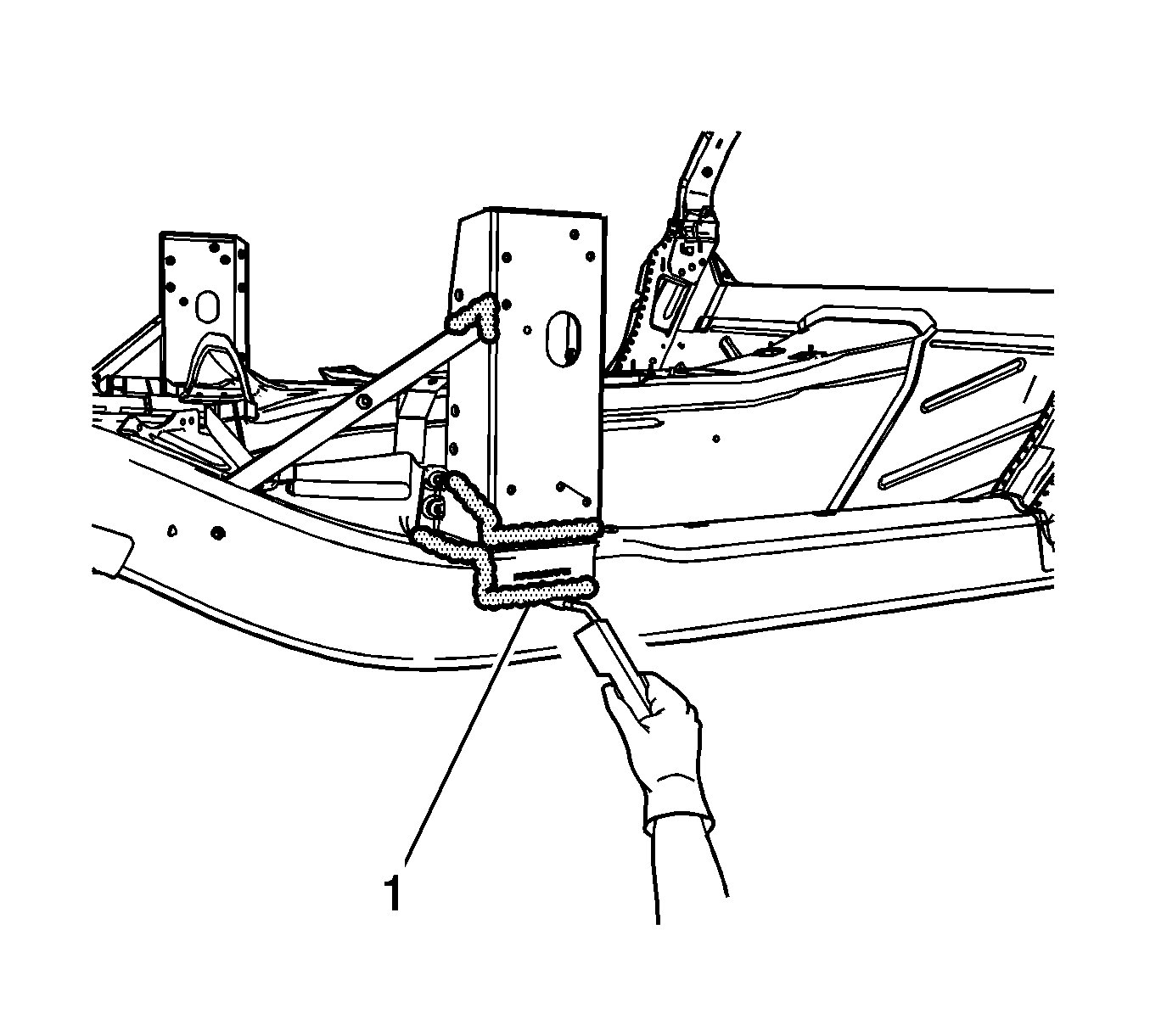
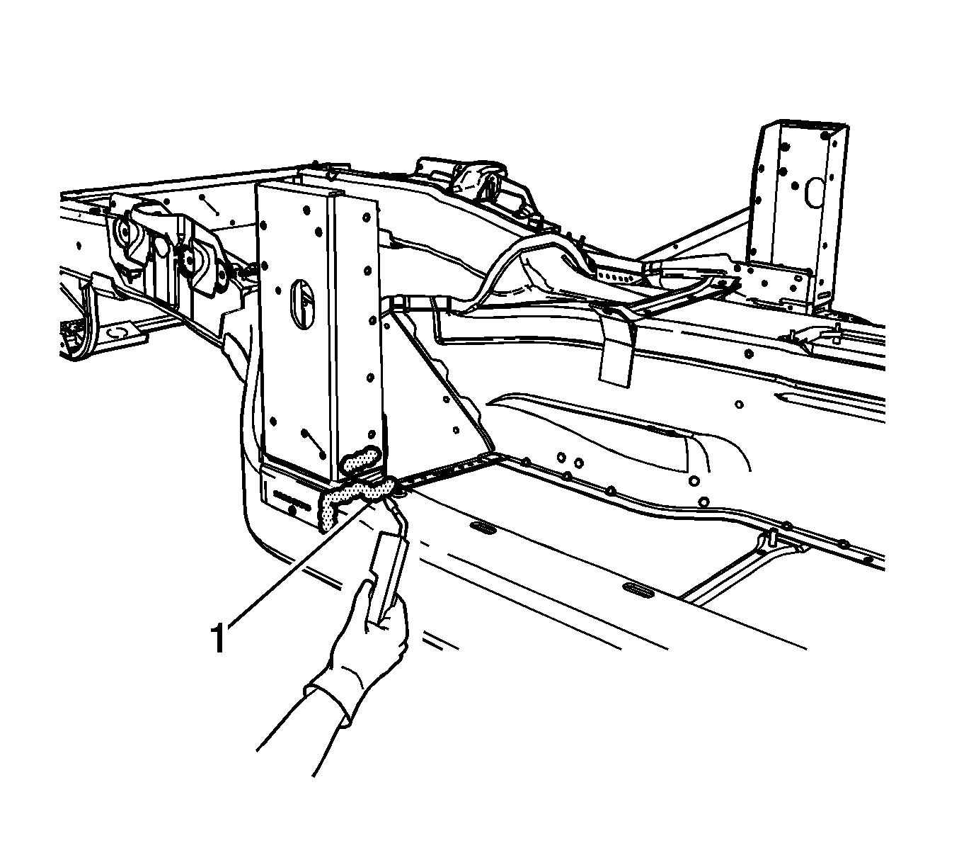
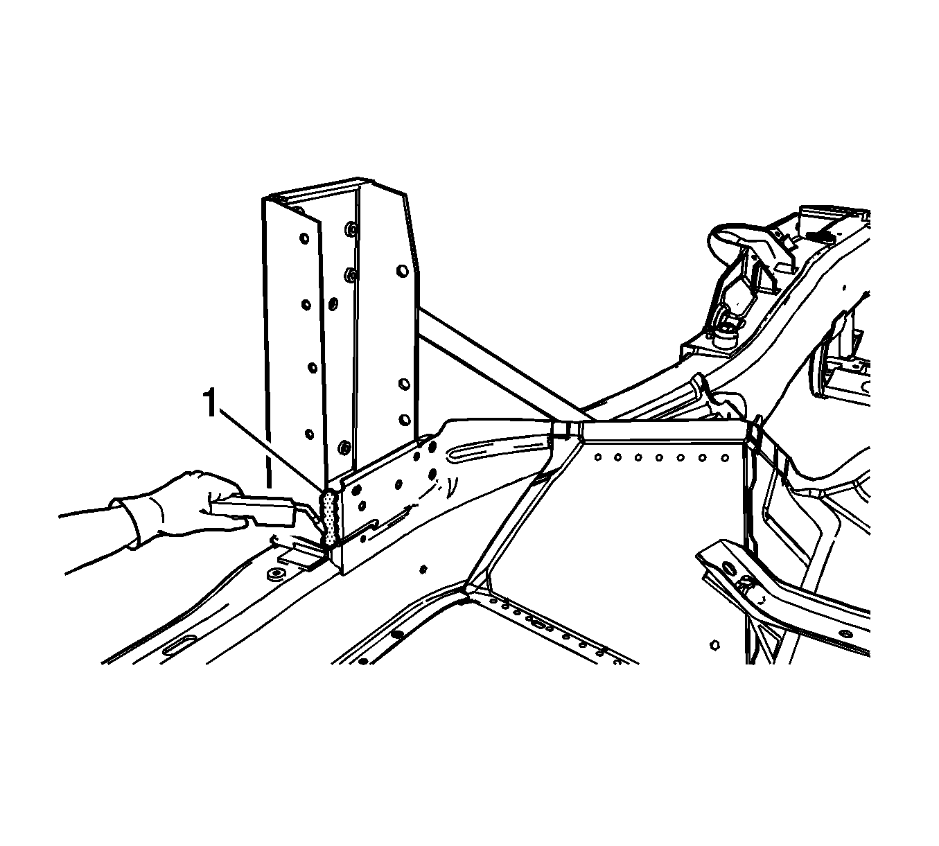
- Apply a consistent bead of structural adhesive 10 mm (3/8 in) in diameter to mate with the bonding surfaces. Refer to Sheet Molded Compound (SMC) Panel Bonding .
- If the weld (1) is not accessible, replace the weld with structural adhesive.
- Apply 3M® Weld-Thru Coating P/N 05916 or equivalent to all mating surfaces.
- Position the hinge pillar to the vehicle using 3-dimensional measuring equipment.
- Install the bolts (1) that attach the windshield frame to the front hinge pillar.
- Using a metal inert gas (MIG) welder, stitch weld (1) the inner hinge pillar to the vehicle in the locations noted on the original panel.
- Using a MIG welder, stitch weld (1) the outer hinge pillar to the vehicle in the locations noted on the original panel.
- Apply the sealers and the anti-corrosion materials to the repair area, as necessary. Refer to Anti-Corrosion Treatment and Repair in Paint and Coatings.
- Paint the repair area. Refer to Basecoat/Clearcoat Paint Systems in Paint and Coatings.
- Install all related panels and components.
- Connect the negative battery cable. Refer to Battery Negative Cable Disconnection and Connection in Engine Electrical.
- Enable the SIR system. Refer to SIR Disabling and Enabling in SIR.
Important: Use primer only on bonding surfaces. Do NOT top coat any bonding surfaces. Refer to the adhesive manufacture's recommendation.
Notice: Refer to Fastener Notice in the Preface section.
Tighten
Tighten the bolts to 25 N·m (18 lb ft).


Front Hinge Pillar Body Replacement Z06
Removal Procedure
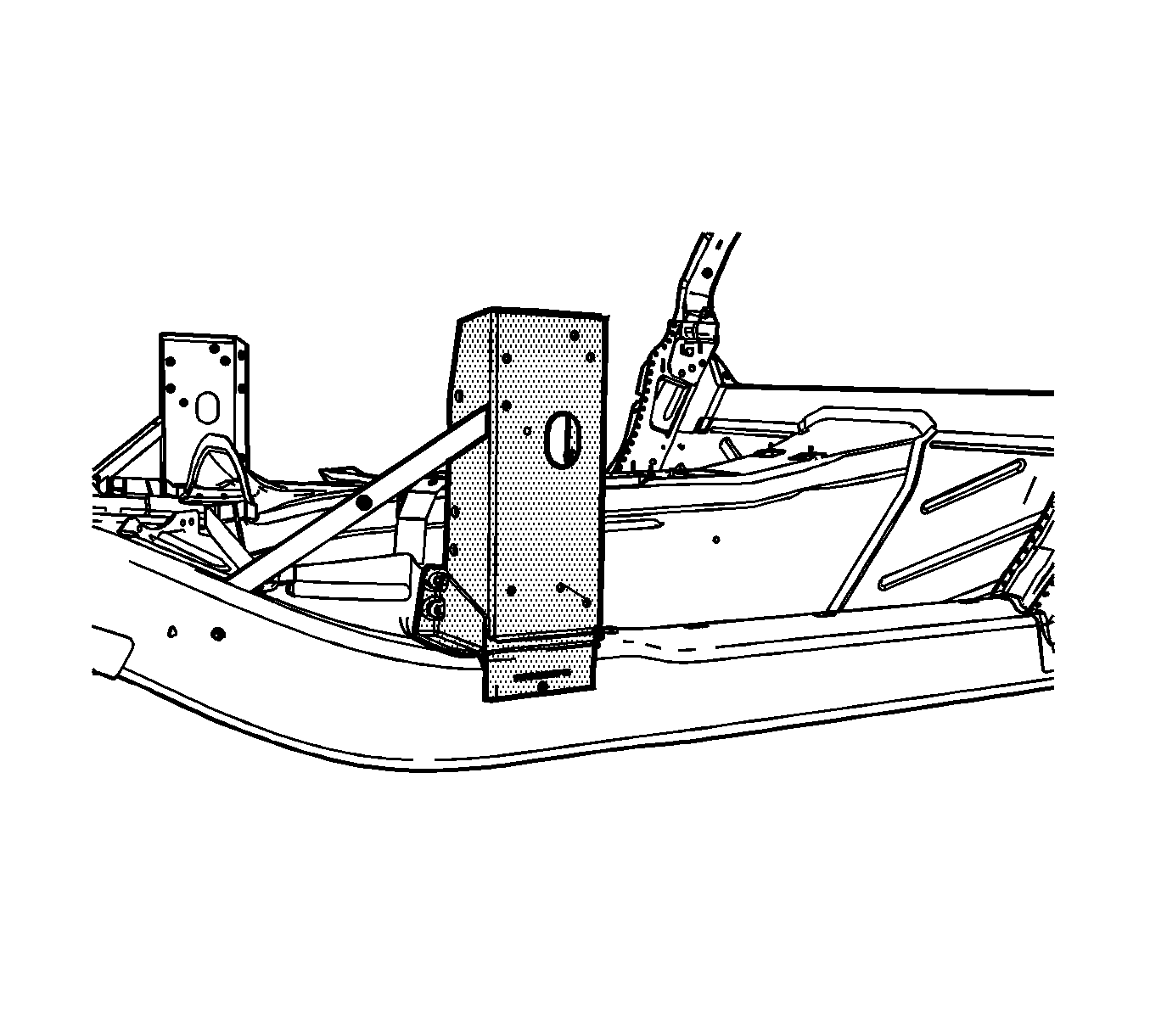
Important: When welding cast aluminum recommend wire alloy is 4043 and the recommend wire size is 0.035. The shielding gas is 100 percent Argon.
The front hinge pillar panel is bolted, welded, and bonded with structural adhesive to the side structure and frame rail. The replacement front hinge pillar panel is comprised of two types of materials. These include 6063 aluminum for the upper panel and A356 cast aluminum for the lower panel. You must remove and replace the side door opening panel in order to replace the front hinge pillar.
- Disable the SIR system. Refer to SIR Disabling and Enabling in SIR.
- Disconnect the negative battery cable. Refer to Battery Negative Cable Disconnection and Connection in Engine Electrical.
- Remove all related panels and components.
- Repair as much of the damage as possible to factory specifications. Refer to Dimensions - Body.
- Note the location of the sealers and the anti-corrosion materials and remove these components from the repair area as necessary. Refer to Anti-Corrosion Treatment and Repair in Paint and Coatings.
- Remove the bolts (1) attaching the front hinge pillar to the windshield frame.
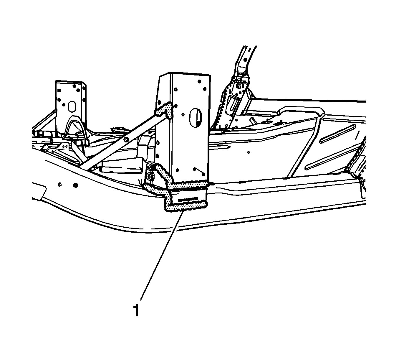
- Locate and remove all factory welds (1) from the front outer hinge pillar. Note the number and location of the welds for installation of the new hinge pillar.
- Locate and remove all factory welds (1) from the rear outer hinge pillar. Note the number and location of the welds for installation of the new hinge pillar.
- Locate and remove all factory welds (1) from the inner hinge pillar. Note the number and location of the welds for installation of the new hinge pillar.
- Remove the damaged hinge pillar.
- Note the location of the adhesive and remove all remaining loose adhesive.
Caution: Refer to Approved Equipment for Collision Repair Caution in the Preface section.

Important: Do NOT damage the inner panels or the reinforcements.
Important: Hand tools, saw blades and abrasives used for aluminum repairs should be dedicated for aluminum only to prevent contamination.
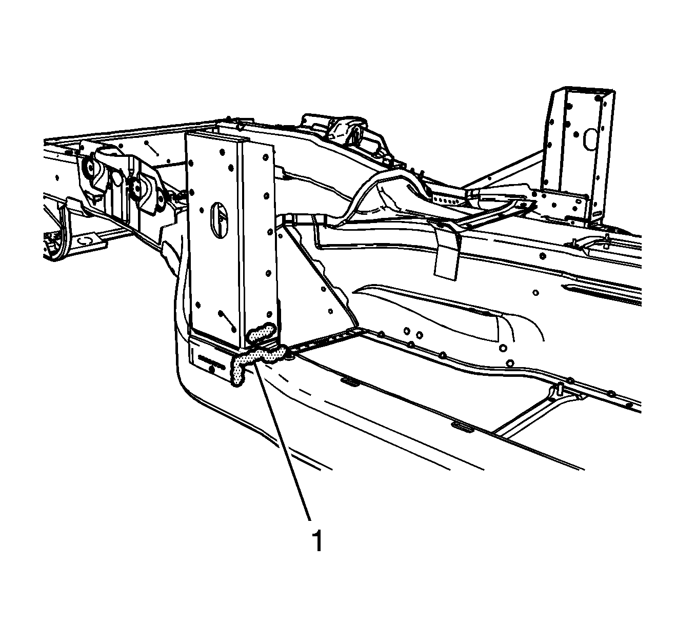
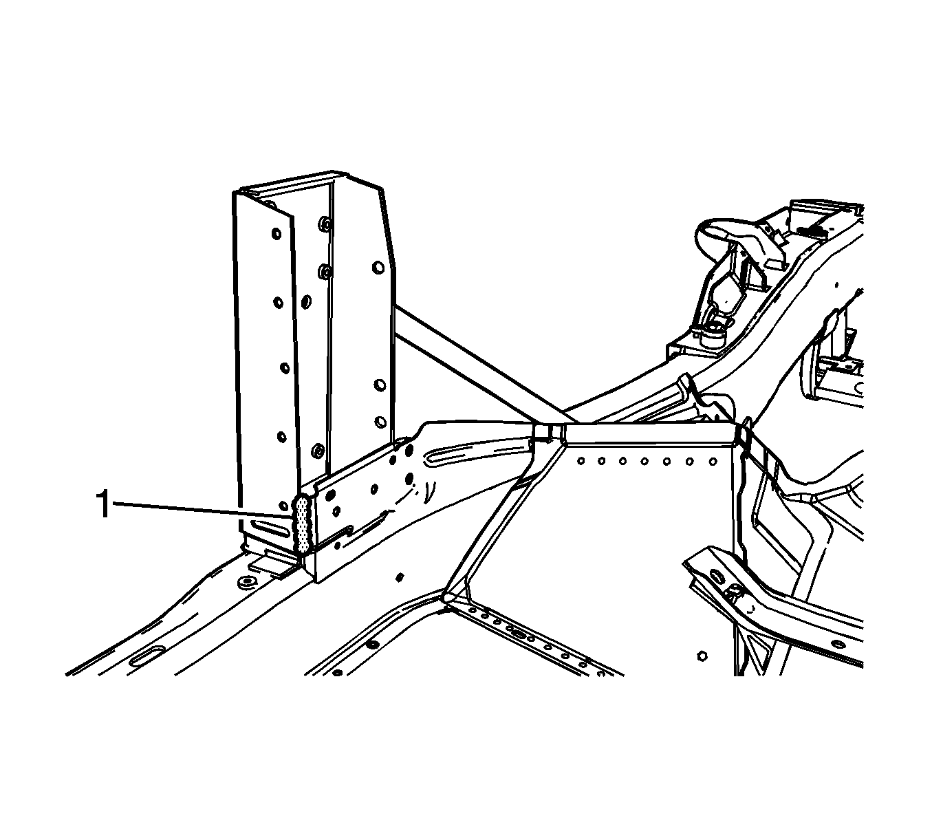

Installation Procedure
- Before applying the adhesive, dry fit the hinge pillar for proper fit and alignment.
- Clean and prepare all bonding mating surfaces according to the adhesive manufacturer's recommendations.
- Apply a consistent bead of structural adhesive 10 mm (3/8 in) in diameter to mate with the bonding surfaces. Refer to Sheet Molded Compound (SMC) Panel Bonding.
- Position the hinge pillar to the vehicle using 3-dimensional measuring equipment.
- Install the bolts (1) that attach the windshield frame to the front hinge pillar.
- Prepare all welding attachment surfaces as necessary.
- Using a PULSED-MIG welder, tack weld the hinge pillar to the vehicle.
- Using a PULED-MIG welder, stitch weld the front outer hinge pillar to the vehicle in the locations noted on the original panel.
- Using a PULED-MIG welder, stitch weld the rear outer hinge pillar to the vehicle in the locations noted on the original panel.
- Using a PULED-MIG welder, stitch weld the inner hinge pillar to the vehicle in the locations noted on the original panel.
- Apply the sealers and the anti-corrosion materials to the repair area, as necessary. Refer to Anti-Corrosion Treatment and Repair in Paint and Coatings.
- Paint the repair area. Refer to Basecoat/Clearcoat Paint Systems in Paint and Coatings.
- Install all related panels and components.
- Connect the negative battery cable. Refer to Battery Negative Cable Disconnection and Connection in Engine Electrical.
- Enable the SIR system. Refer to SIR Disabling and Enabling in SIR.
Important: Use primer only on bonding surfaces. Do NOT top coat any bonding surfaces. Refer to the adhesive manufacture's recommendation.

Notice: Refer to Fastener Notice in the Preface section.
Tighten
Tighten the bolts to 25 N·m (18 lb ft).
Important: Use a stainless steel brush to remove the oxide layer prior to welding.
Important: Recommend wire alloy is 4043 and wire size is 0.035. The shielding gas is 100 percent Argon. A 2 minute cooling down period is recommend for every 2 minutes or 100 mm (4 in) of welding.
