GM Service Manual Online
For 1990-2009 cars only

Tools Required

    • J 24319-B Steering Linkage and Tie Rod Puller
    • J 45341 Rear Wheel Drive Shaft Removal Tool
    • J-2619-A Slide Hammer
    • J 44394 Axle Seal Protector
    • J 45059 Angle Meter

Removal Procedure


    Object Number: 1625417  Size: SH
  1. Raise the hood.
  2. Disconnect the negative battery cable. Refer to Battery Negative Cable Disconnection and Connection .
  3. Remove the air cleaner assembly. Refer to Air Cleaner Assembly Replacement .
  4. Relieve the fuel system pressure. Refer to Fuel Pressure Relief .
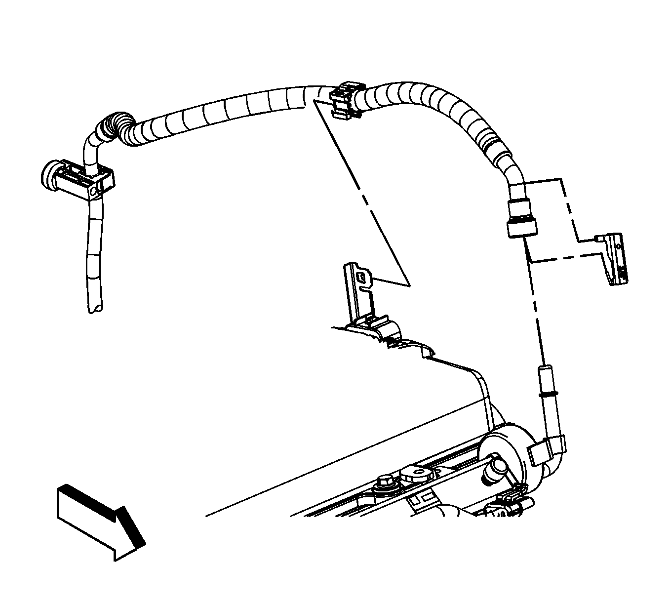
  5. Disconnect the fuel feed line from the fuel rail. Refer to Metal Collar Quick Connect Fitting Service .

  6. Object Number: 1625606  Size: SH
  7. Disconnect the evaporative emission (EVAP) line from the EVAP purge solenoid. Refer to Plastic Collar Quick Connect Fitting Service .
  8. Remove the windshield washer solvent reservoir. Refer to Windshield Washer Solvent Container Replacement .
  9. Drain the cooling system. Refer to Cooling System Draining and Filling .
  10. Remove the engine drive belt. Refer to Drive Belt Replacement .
  11. Remove the left side engine splash shield. Refer to Engine Splash Shield Replacement .
  12. Remove the catalytic converter. Refer to Catalytic Converter Replacement .

  13. Object Number: 1625478  Size: SH
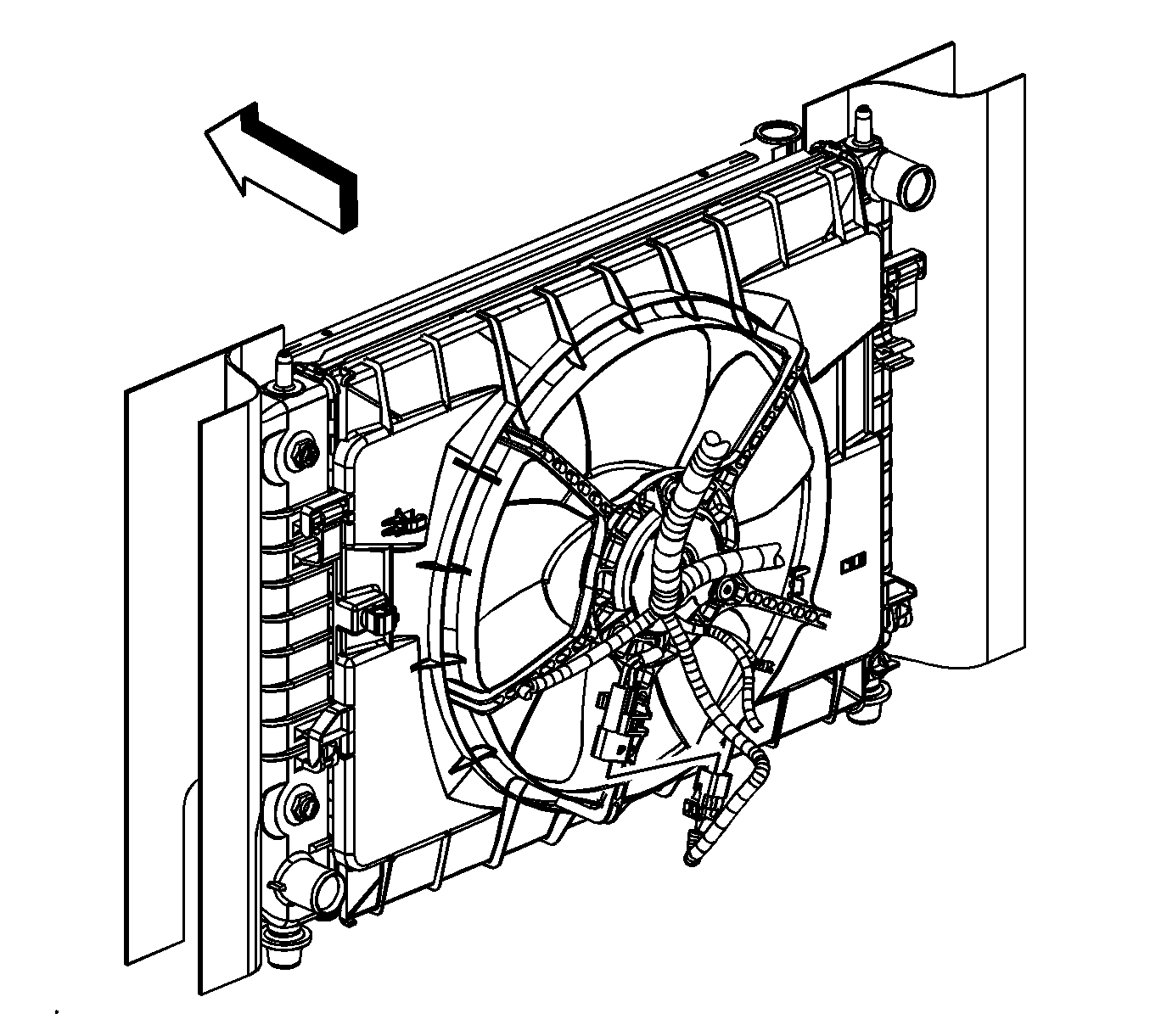
  14. Disconnect the cooling fan electrical connector.
  15. Lower the vehicle.

  16. Object Number: 1631889  Size: SH
  17. Remove the engine control module (ECM)/transaxle control module (TCM) cover.

  18. Object Number: 1639226  Size: SH
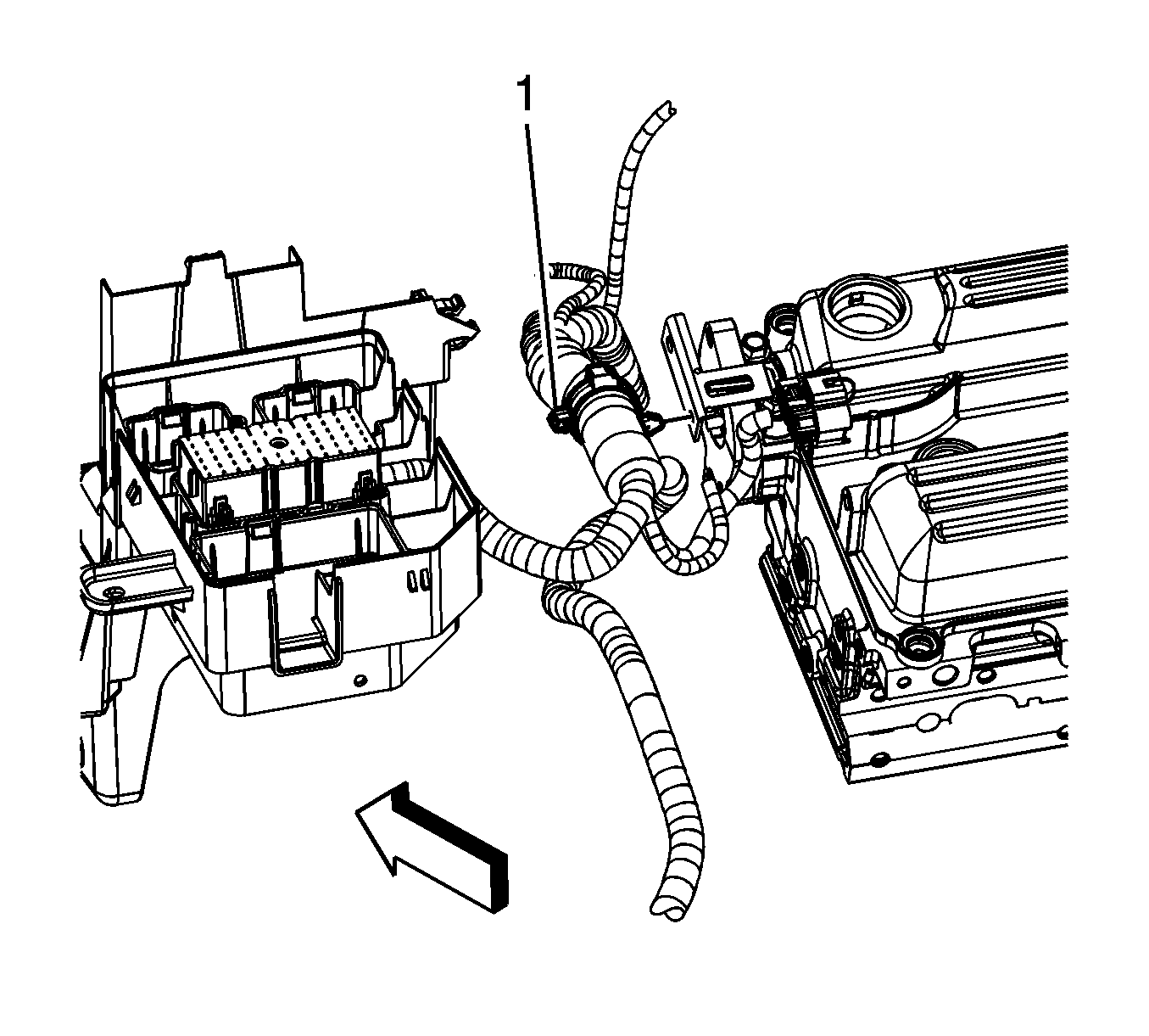
  19. Disconnect the body harness electrical connector (1) from the ECM.

  20. Object Number: 1639228  Size: SH
  21. Disconnect the engine harness electrical connectors (1, 2) from the ECM.

  22. Object Number: 1631518  Size: SH
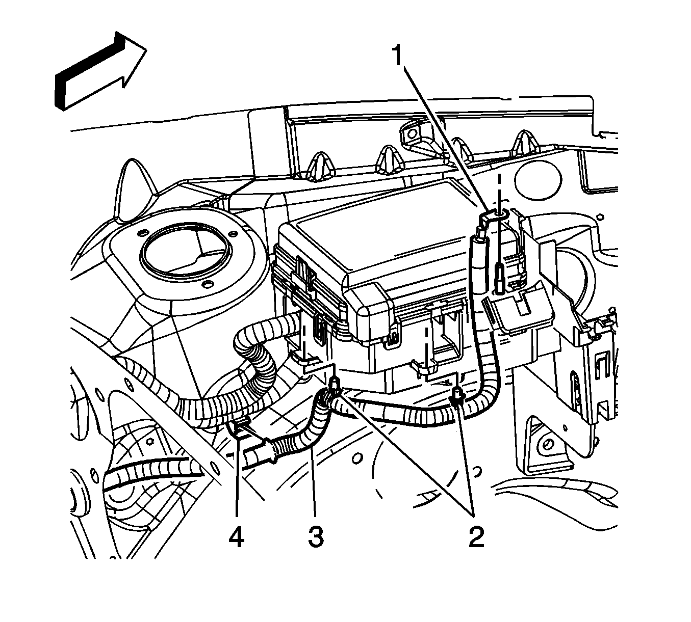
  23. Open the junction block terminal cover.
  24. Remove the junction block terminal nut (1).
  25. Remove the positive/negative battery cable terminal (2) from the stud.

  26. Object Number: 1631516  Size: SH
  27. Remove the positive battery cable terminal (1) from the junction block stud.
  28. Reposition the engine harness as necessary to access the ECM bracket lower bolts.

  29. Object Number: 1720487  Size: SH
  30. Remove the ECM bracket nuts (1) and bolts (2).
  31. Lift the ECM bracket off of the studs and secure the bracket out of the way.

  32. Object Number: 1625418  Size: SH
  33. Reposition the radiator inlet hose clamp at the engine.
  34. Remove the radiator inlet hose from the engine.

  35. Object Number: 1625517  Size: SH
  36. Disconnect the evaporative emission (EVAP) purge solenoid electrical connector (1).

  37. Object Number: 1625460  Size: SH
  38. Remove the engine harness clip (1) from the EVAP purge solenoid bracket.

  39. Object Number: 1631170  Size: SH
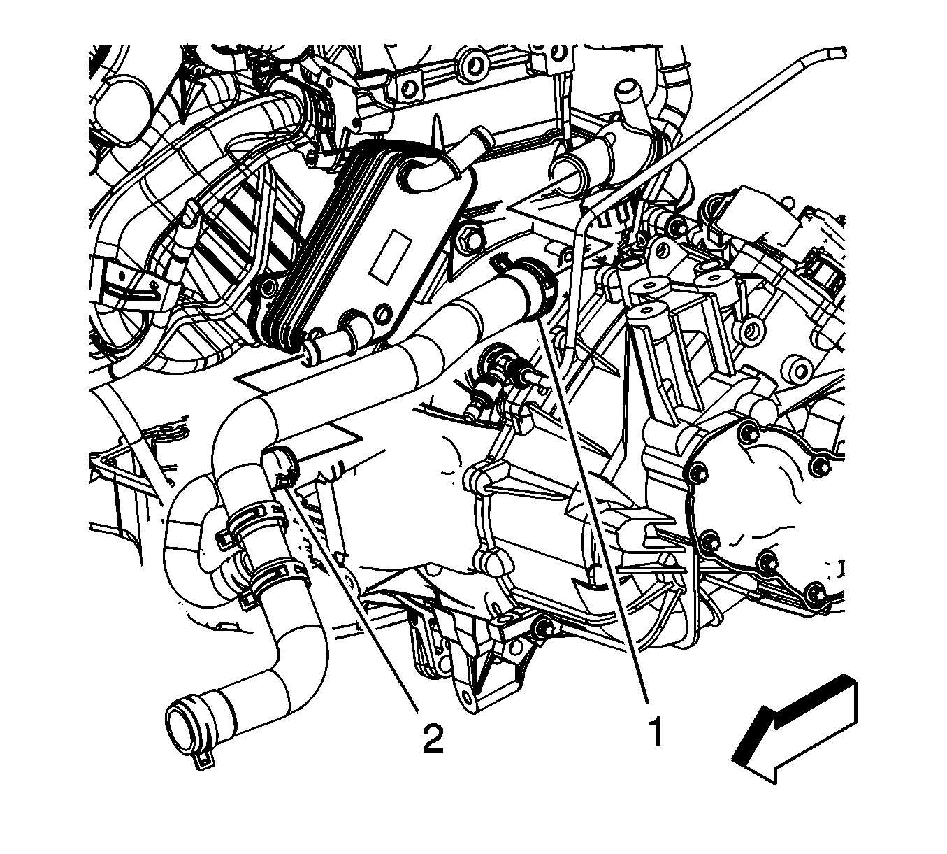
  40. If the vehicle is equipped with a engine oil cooler perform the following steps, reposition the radiator outlet hose clamp (1) at the water outlet.
  41. Reposition the radiator outlet hose clamp (2) at the oil cooler.
  42. Remove the radiator outlet hose from the water outlet.
  43. Remove the radiator outlet hose from the oil cooler

  44. Object Number: 1713958  Size: SH
  45. If the vehicle is not equipped with a engine oil cooler, reposition the radiator outlet hose clamp at the engine.
  46. Remove the radiator outlet hose from the engine.

  47. Object Number: 1639712  Size: SH
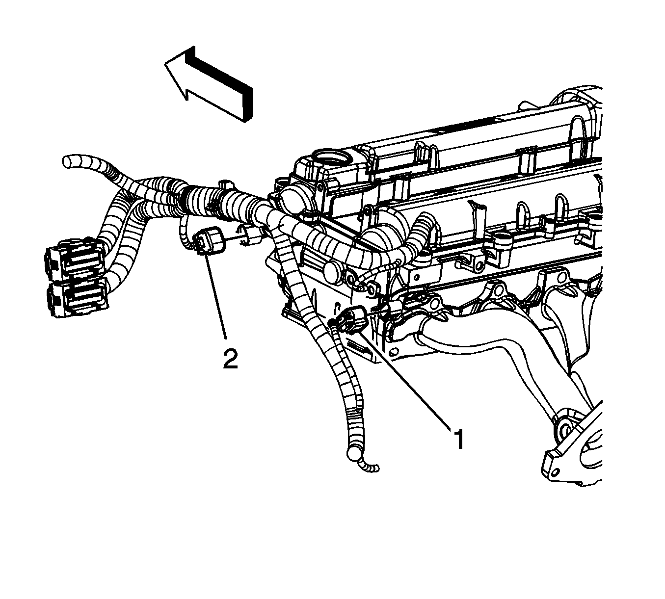
  48. Disconnect the intake (2) and exhaust (1) camshaft position (CMP) sensor electrical connectors.

  49. Object Number: 1625419  Size: SH
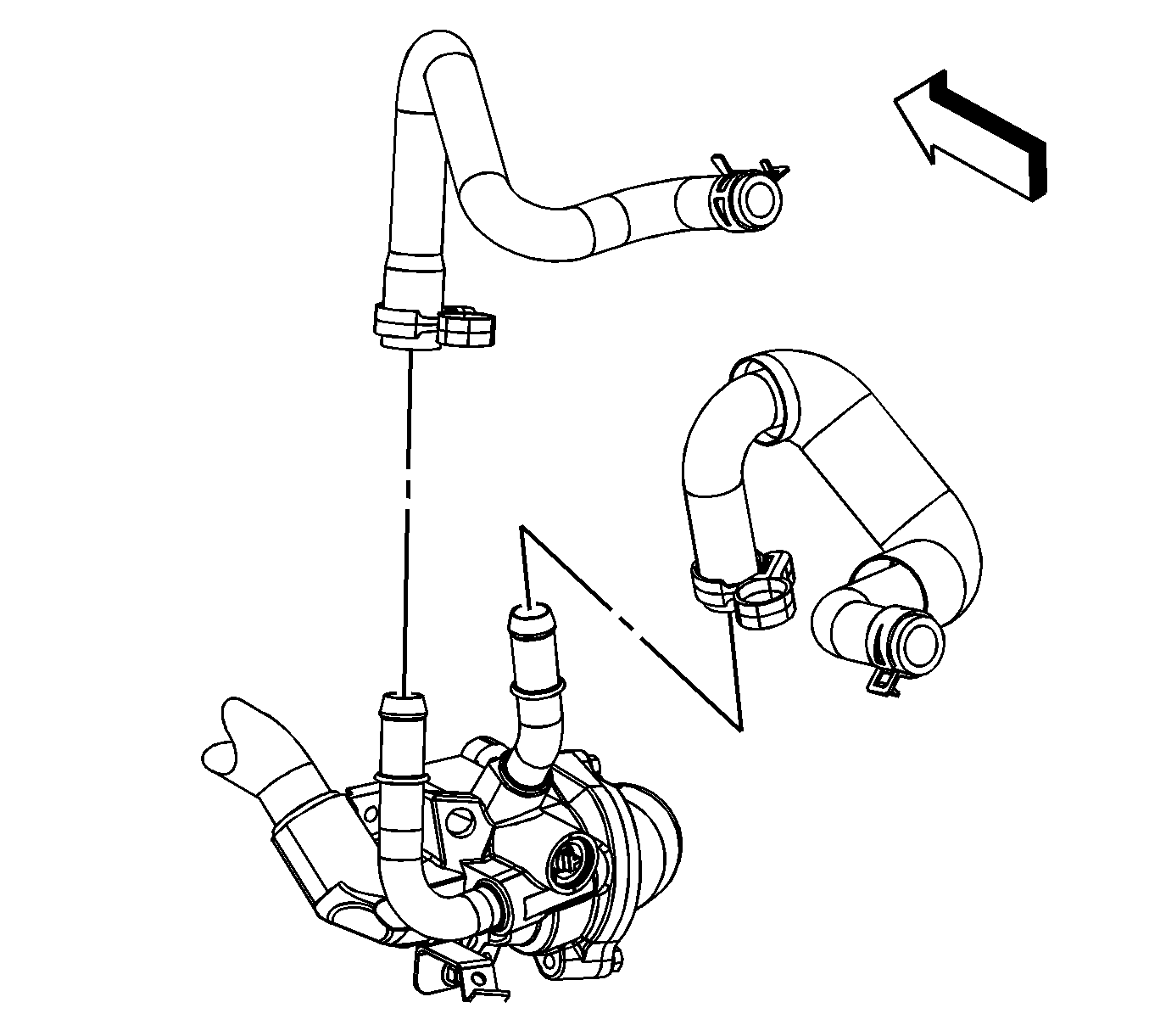
  50. Reposition the heater inlet and outlet hose clamps at the thermostat housing.
  51. Remove the heater inlet and outlet hoses from the thermostat housing.

  52. Object Number: 1625669  Size: SH
  53. Disconnect the engine coolant heater cord, if necessary.

  54. Object Number: 1625676  Size: SH
  55. Remove the engine coolant heater cord straps from the engine harness, if equipped.
  56. Reposition the engine coolant heater cord out of the way, if equipped.

  57. Object Number: 1628035  Size: SH
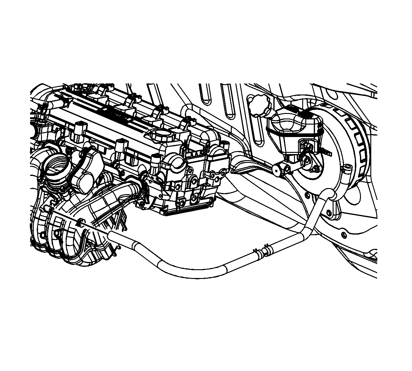
  58. Reposition the brake booster vacuum hose clamp at the intake manifold.
  59. Remove the brake booster vacuum hose from the intake manifold. Reposition the hose.

  60. Object Number: 1623764  Size: SH
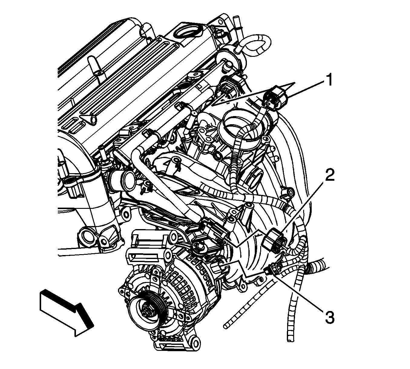
  61. Disconnect the following electrical connectors:
  62. •  Throttle actuator control (TAC) (1)
    • Manifold absolute pressure (MAP) sensor
    • Fuel injector harness (2)
    • Generator (3)

    Object Number: 1628020  Size: SH
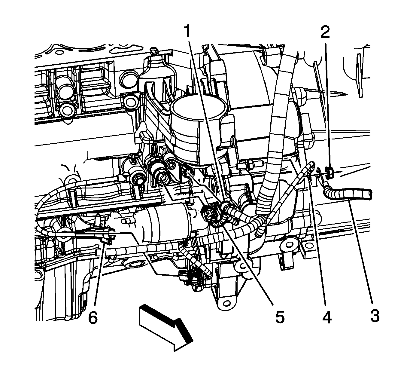
  63. Disconnect the ignition coils electrical connectors (3).
  64. Disconnect the intake (2) and exhaust (1) camshaft position actuator electrical connectors.

  65. Object Number: 1631141  Size: SH
  66. Remove the engine harness clips (1, 2) from the camshaft cover.

  67. Object Number: 1625463  Size: SH
  68. Remove the engine harness clip nut (2).
  69. Remove the engine harness clip (1) from the transaxle stud.

  70. Object Number: 1627740  Size: SH
  71. Remove the engine harness clip (1) from the oil level indicator tube bracket.
  72. Raise and support the vehicle. Refer to Lifting and Jacking the Vehicle .
  73. Remove the engine harness clips (2, 4) from the intake manifold.

  74. Object Number: 1622787  Size: SH
  75. Remove the starter. Refer to Starter Motor Replacement .
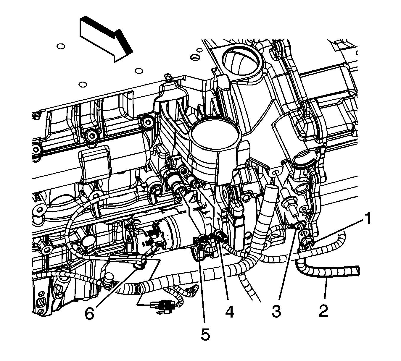
  76. If equipped with a automatic transaxle perform the following steps, remove the positive/negative battery cable ground nut (1).
  77. Remove the positive/negative cable (2) terminal from the stud.
  78. Remove the engine harness ground terminal (3) from the stud.
  79. Disconnect the following electrical connectors:
  80. • Crankshaft position (CKP) sensor (4)
    • Oil pressure sensor (5)
    • Knock sensor (6)

    Object Number: 1622807  Size: SH
  81. If equipped with a manual transaxle perform the following steps, remove the positive/negative battery cable ground nut (2).
  82. Remove the positive/negative cable (3) terminal from the stud.
  83. Remove the engine harness ground terminal (4) from the stud.
  84. Disconnect the following electrical connectors:
  85. • Crankshaft position (CKP) sensor (1)
    • Oil pressure sensor (5)
    • Knock sensor (6)

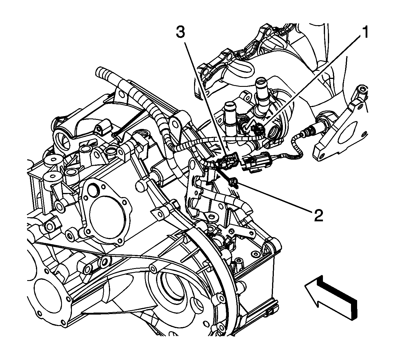
    Object Number: 1625475  Size: SH
  86. Disconnect the air conditioning (A/C) pressure switch electrical connector (1).
  87. Disconnect the A/C compressor electrical connector (2).
  88. Unbolt and reposition the AC compressor aside. Secure the compressor with tie straps or mechanics wire.
  89. Drain the engine oil. Refer to Engine Oil and Oil Filter Replacement .

  90. Object Number: 1625472  Size: SH
  91. Remove the engine harness ground bolt (7).
  92. Remove the engine harness ground (8) from the engine block.
  93. Lower the vehicle.
  94. Remove the generator nut (2).
  95. Remove the engine harness lead terminal (1) from the generator.

  96. Object Number: 1625484  Size: SH
  97. If equipped with a automatic transaxle perform the following steps, remove the engine harness clip nut (2) from the engine stud.
  98. Remove the engine harness clip (1) from the stud.
  99. Disconnect the vehicle speed sensor (VSS) electrical connector (4).
  100. Remove the engine harness clip (3) from the speed sensor.

  101. Object Number: 1625479  Size: SH
  102. If equipped with a automatic transaxle, disconnect the engine harness from the transaxle.

  103. Object Number: 1625483  Size: SH
  104. If equipped with a automatic transaxle, perform the following steps, disconnect the engine coolant temperature (ECT) sensor electrical connector (1).
  105. Remove the connector position assurance (CPA) retainer (2).
  106. Disconnect the engine harness electrical connector (3) from the heater oxygen sensor (HO2S).

  107. Object Number: 1625486  Size: SH
  108. If equipped with a manual transaxle, perform the following steps, disconnect the ECT sensor electrical connector (1).
  109. Remove the CPA retainer (2).
  110. Disconnect the engine harness electrical connector (3) from the HO2S.

  111. Object Number: 1625487  Size: SH
  112. If equipped with a automatic transaxle, perform the following steps, remove the CPA retainer (5).
  113. Disconnect the engine harness electrical connector (6) from the park neutral position switch.
  114. Remove the engine harness clip (1) from the transaxle stud.
  115. Remove the CPA retainer (2).
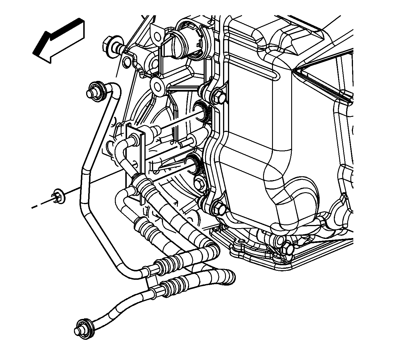
  116. Remove the engine harness electrical connector clip (4) from the transaxle rear mount bracket.
  117. Disconnect the engine harness electrical connector (3) from the HO2S.

  118. Object Number: 1625489  Size: SH
  119. If equipped with a manual transaxle, disconnect the engine harness electrical connector (1) from the VSS.
  120. Remove the engine harness clip (2) from the transaxle.
  121. Remove the CPA retainer (3).
  122. Remove the engine harness electrical connector clip (5) from the transaxle rear mount bracket.
  123. Disconnect the engine harness electrical connector (4) from the HO2S.
  124. Disconnect the engine harness electrical connector (7) from the back up lamp switch.
  125. Remove the engine harness clip (6) from the transaxle.
  126. Gather all engine harness branches are reposition the harness off to the side, out of the way.

  127. Object Number: 1625581  Size: SH
  128. If equipped with a automatic transaxle, disconnect the range selector lever cable from the transaxle lever.
  129. Remove the range selector lever cable from the transaxle bracket.

  130. Object Number: 1625583  Size: SH
  131. If equipped with a manual transaxle, disconnect the range selector and shift lever cables from the transaxle levers.
  132. Remove the range selector and shift lever cables from the transaxle bracket.

  133. Object Number: 1720383  Size: SH
  134. if equipped with a automatic transaxle, remove the oil cooler line nut.
  135. Remove the oil cooler lines from the transaxle.

  136. Object Number: 1720288  Size: SH
  137. Remove the left and right stabilizer link to strut nuts.
  138. Separate the stabilizer links from the struts. (left side shown, right side similar).

  139. Object Number: 1720289  Size: SH
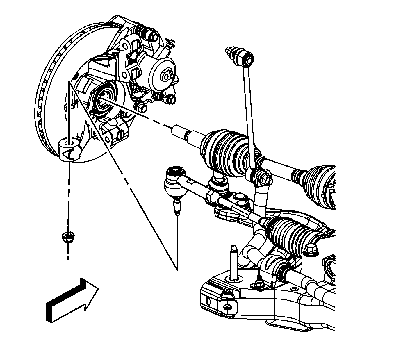
  140. Remove the left and right steering gear outer tie rod to knuckle nuts. Discard the nuts.
  141. Using the J 24319-B , separate the outer tie rods from the steering knuckles. (left side shown, right side similar).

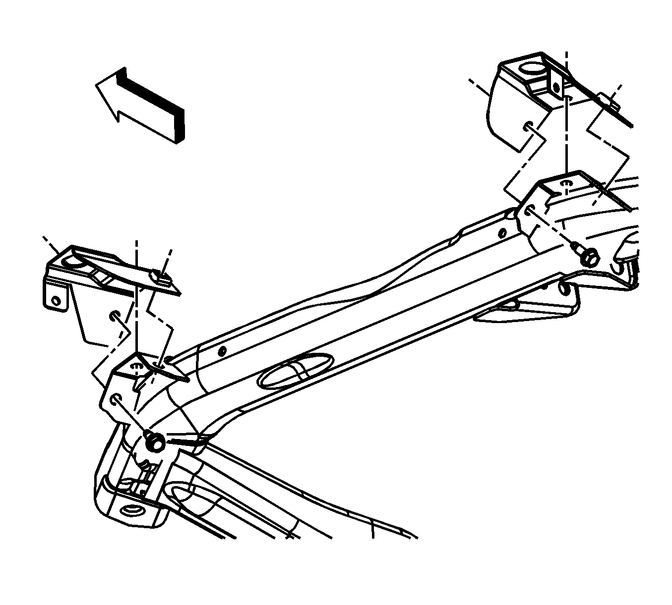
  142. Object Number: 1720286  Size: SH
  143. Remove the left and right ball joint to steering knuckle bolts and nuts.
  144. Separate the lower ball joints from the steering knuckles. (left side shown, right side similar).

  145. Object Number: 1720291  Size: SH
  146. Assemble the J 45341 and the J-2619-A .
  147. Using the J 45341 and the J-2619-A , separate the right wheel drive shaft from the transaxle. Repeat for the left side.
  148. Secure the wheel drive shafts out of the way.

  149. Object Number: 1720381  Size: SH
  150. Remove the lower radiator support bolts.
  151. Secure the radiator assembly to the radiator core support with bungee cords.

  152. Object Number: 1623160  Size: SH
  153. Lower the vehicle to about 3 feet off the ground.
  154. Position a engine lift table under the frame.
  155. Place wood blocks on top of the lift table between the table and the frame.
  156. Lower the vehicle until the frame is resting on the blocks of wood.
  157. Remove the engine mount bracket bolts.

  158. Object Number: 1623167  Size: SH
  159. Remove the transaxle mount to transaxle bolts.

  160. Object Number: 1625598  Size: SH
  161. Remove the frame bolts using the following sequence:
  162. 117.1. Remove the front frame bolts.
    117.2. Remove the rear frame bolts.
  163. Slowly raise the vehicle up away from the powertrain assembly.
  164. Slide the lift table out from under the vehicle.
  165. Attach an engine lift hoist to the engine lift hooks.

  166. Object Number: 1625720  Size: SH
  167. If equipped with a automatic transaxle, remove the torque converter housing access plug.

  168. Object Number: 1625721  Size: SH
  169. If equipped with a automatic transaxle, remove the torque converter bolts.

  170. Object Number: 1625684  Size: SH
  171. If equipped with a automatic transaxle, remove the transaxle brace bolts and brace.

  172. Object Number: 1625687  Size: SH
  173. If equipped with a manual transaxle, remove the transaxle to engine bolts/stud.

  174. Object Number: 1625689  Size: SH
  175. If equipped with a automatic transaxle, remove the transaxle to engine bolts/stud.
  176. Separate the engine from the transaxle.
  177. If equipped with a manual transaxle, remove the clutch pressure plate and disc. Refer to Clutch Pressure and Driven Plate Replacement .
  178. Remove the following components:
  179. • The engine mount bracket
    • The engine block heater, if equipped
    • The generator
  180. Using the engine hoist, install the engine to a suitable engine stand.

Installation Procedure


    Object Number: 1625689  Size: SH
  1. Using a engine hoist, remove the engine from the engine stand.
  2. Install the following components:
  3. • The engine mount bracket
    • The engine block heater, if equipped
    • The generator
  4. If equipped with a manual transaxle, install the clutch pressure plate and disc. Refer to Clutch Pressure and Driven Plate Replacement .
  5. Install the engine to the transaxle.
  6. Notice: Refer to Fastener Notice in the Preface section.

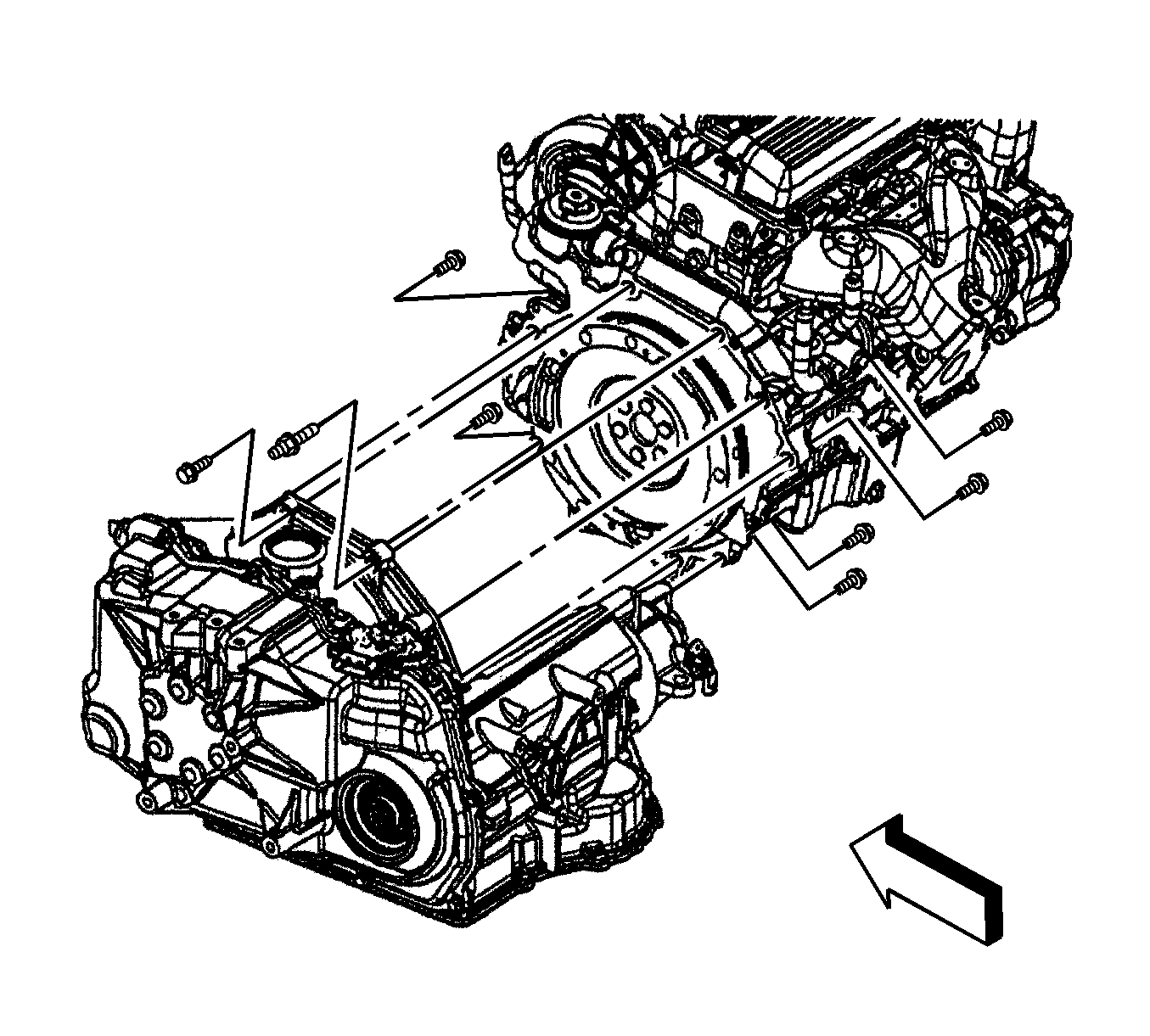
  7. If equipped with a automatic transaxle, install the transaxle to engine bolts/stud.
  8. Tighten
    Tighten the bolt/stud to 75 N·m (55 lb ft).

    Object Number: 1625687  Size: SH
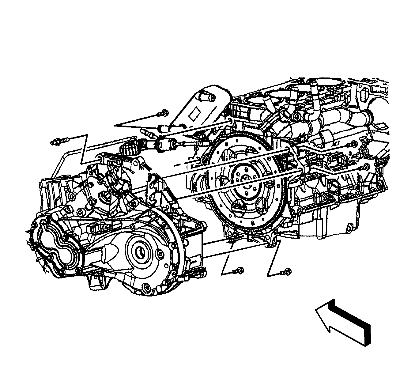
  9. If equipped with a manual transaxle, install the transaxle to engine bolts/stud.
  10. Tighten
    Tighten the bolt/stud to 75 N·m (55 lb ft).

    Object Number: 1625684  Size: SH
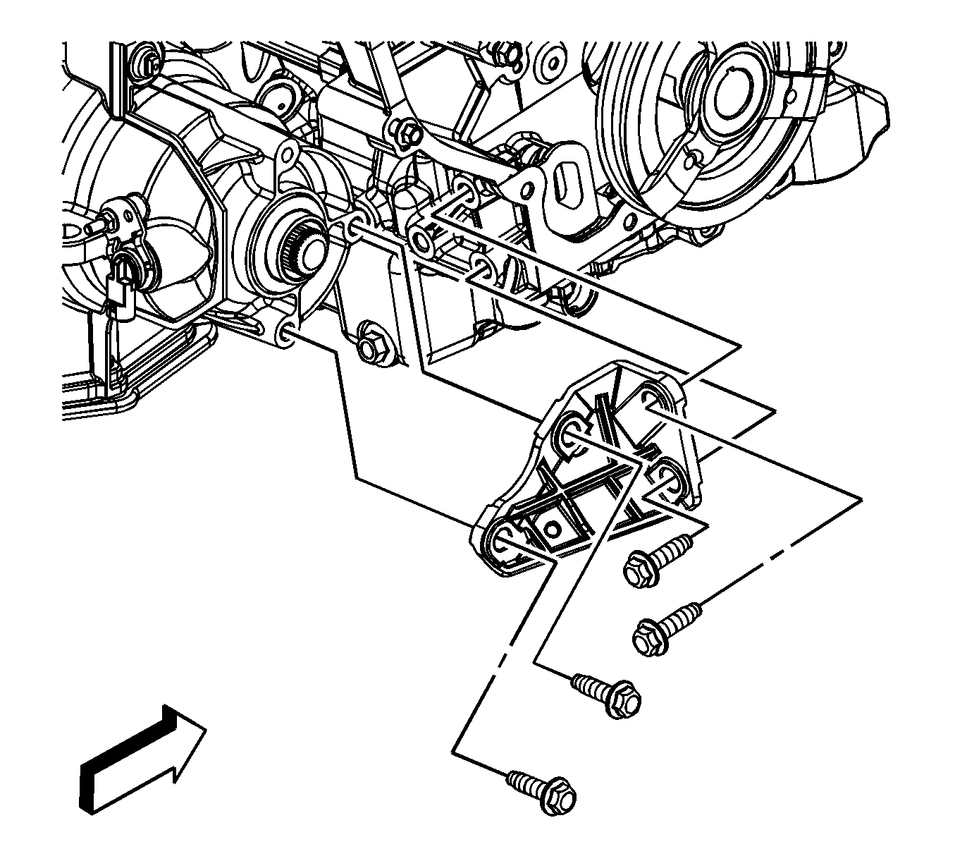
  11. if equipped with a automatic transaxle, install the transaxle brace and bolts.
  12. Tighten
    Tighten the bolts to 50 N·m (37 lb ft).

    Object Number: 1625721  Size: SH
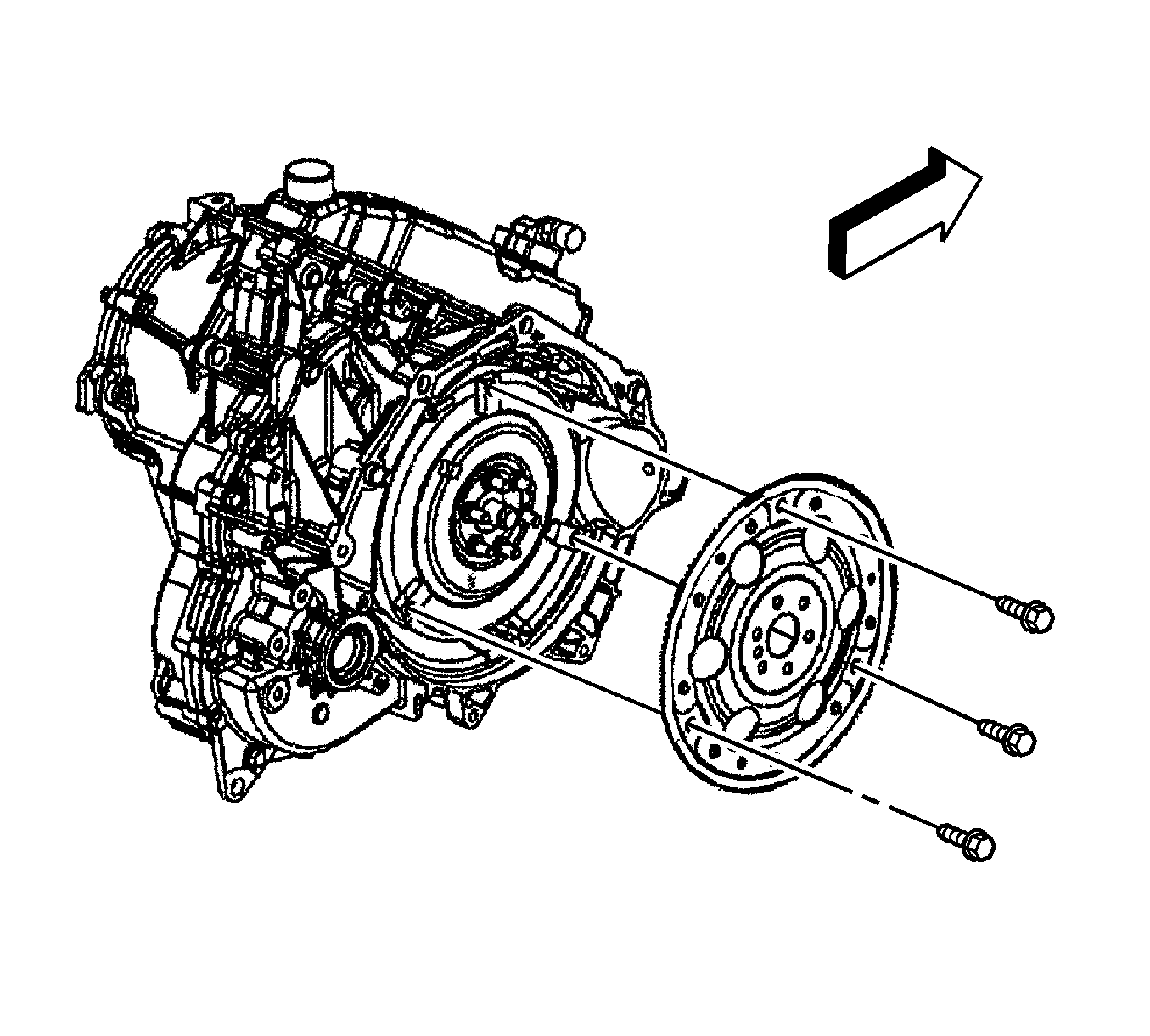
  13. If equipped with a automatic transaxle, install the torque converter bolts.
  14. Tighten
    Tighten the bolts to 62 N·m (46 lb ft).
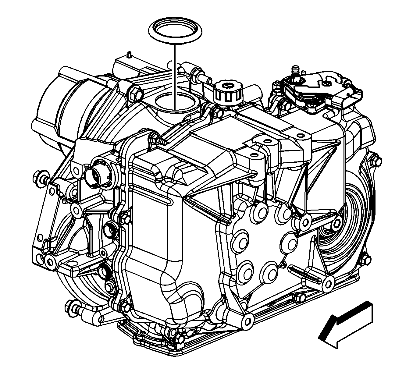

    Object Number: 1625720  Size: SH
  15. If equipped with a automatic transaxle, install the torque converter housing access plug.
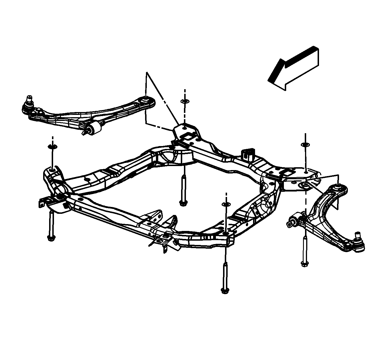
  16. Object Number: 1625598  Size: SH
  17. Remove the engine lift hoist from the engine lift hooks.
  18. Slide the lift table under the vehicle.
  19. Slowly lower the vehicle until the frame bolts align with the holes in the body.
  20. Install the frame bolts.
  21. Tighten
    Tighten the bolts to 100 N·m (74 lb ft) plus an additional 180 degrees using the J 45059 .
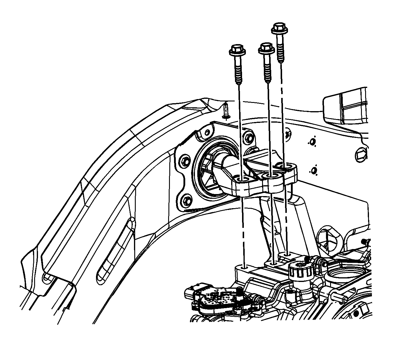

    Object Number: 1623167  Size: SH
  22. Install the transaxle mount to transaxle bolts.
  23. Tighten the transaxle mount to transaxle bolts in the following sequence.
  24. 15.1. Rear
    15.2. Middle
    15.3. Front

    Tighten
    Tighten the bolts to 50 N·m (37 lb ft) .
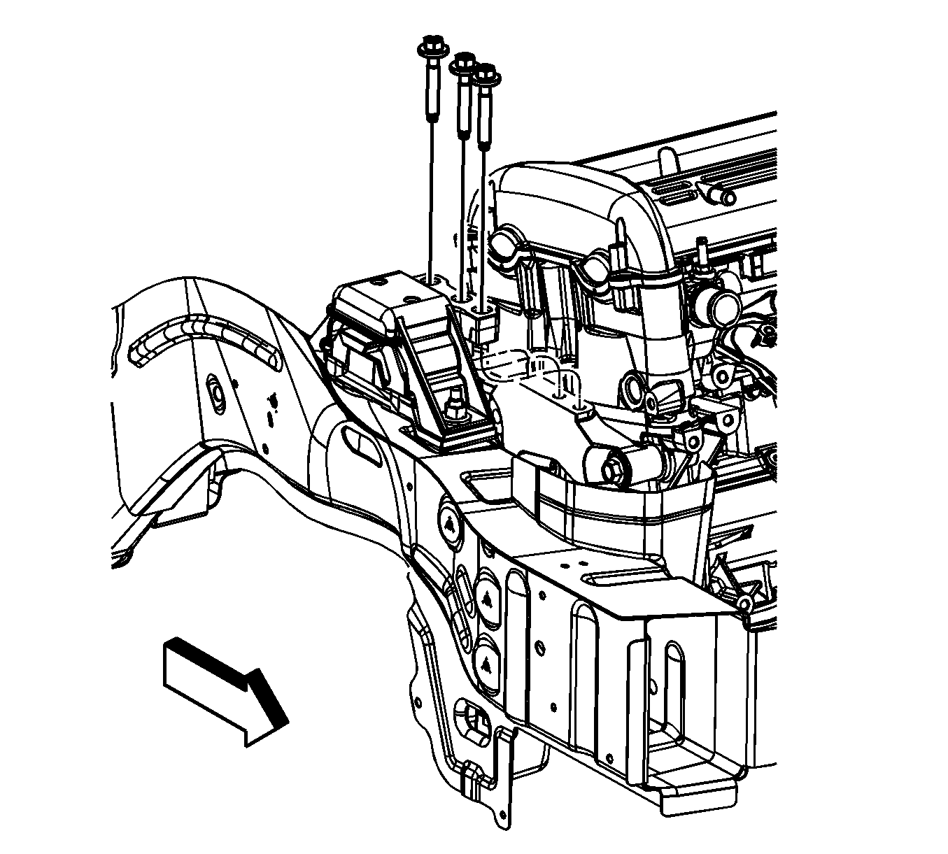

    Object Number: 1623160  Size: SH
  25. Install the engine mount bracket bolts.
  26. Tighten the engine mount to bracket bolts in the following sequence.
  27. 17.1. Middle
    17.2. Rear
    17.3. Front

    Tighten
    Tighten the bolts to 50 N·m (37 lb ft) .

  28. Raise the vehicle until the lift table can be removed from under the vehicle.
  29. Remove the lift table.

  30. Object Number: 1720381  Size: SH
  31. Unsecure the radiator assembly from the radiator core support.
  32. Install the lower radiator support bolts.
  33. Tighten
    Tighten the bolts to 34 N·m (25 lb ft) .
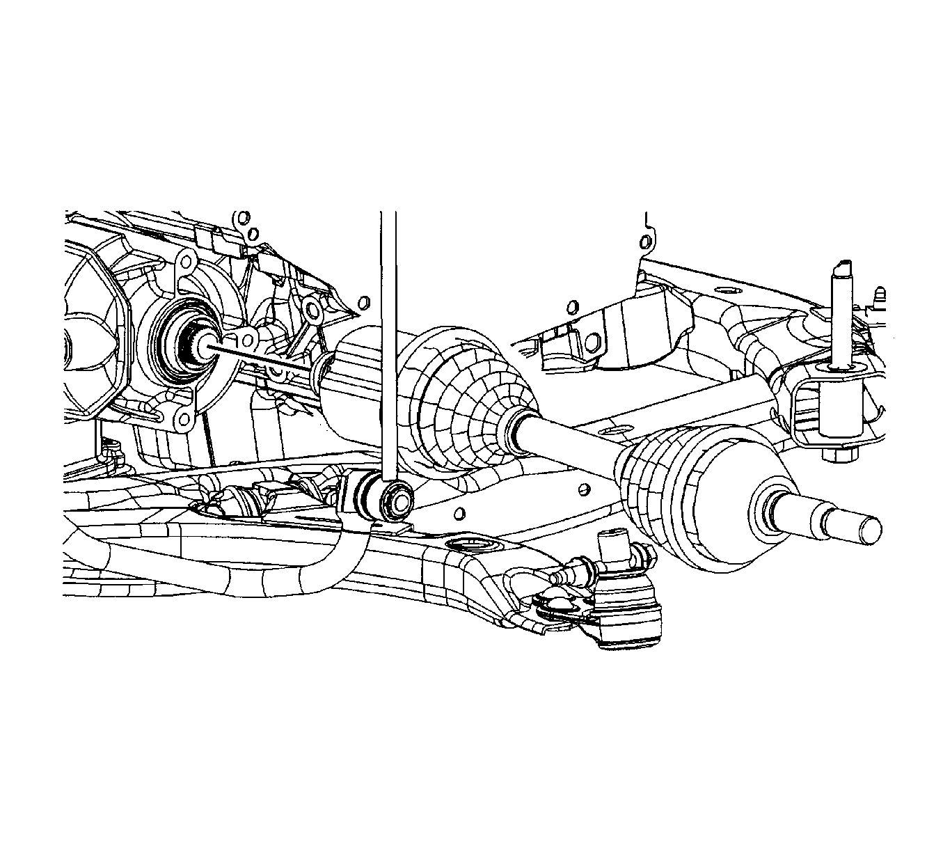

    Object Number: 1720291  Size: SH
  34. Unsecure the wheel drive shaft.
  35. Install the J 44394 into the right transaxle output shaft seal.
  36. Install the right wheel drive shaft into the transaxle until the drive shaft splines are past the seal, remove the J 44394 , then fully install the drive shaft.
  37. Verify that the wheel drive shaft is properly engaged:
  38.    - Grasp the inner tripot housing and pull the inner housing outward. Do NOT pull on the wheel drive shaft.
       - The wheel drive shaft will remain firmly in place when properly engaged.
  39. Repeat steps 22 through 25 for the left side.
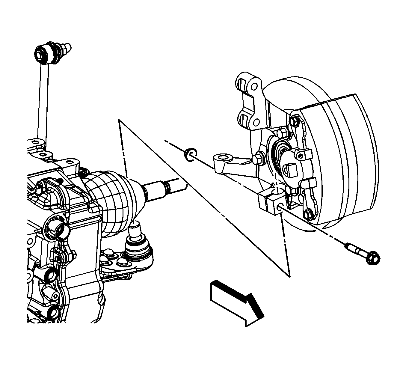
  40. Object Number: 1720286  Size: SH
  41. Install the left and right lower ball joints to the steering knuckles.
  42. Install the ball joint to steering knuckle bolts and nuts.
  43. Tighten

        • Tighten the nut a first pass to 50 N·m (37 lb ft), then loosen the nut 3/4 of a turn.
        • Tighten the nut a final pass to 50 N·m (37 lb ft) plus an additional 30 degrees using the J 45059 .

    Object Number: 1720289  Size: SH
  44. Install the left and right outer tie rods to the steering knuckles.
  45. Install the NEW left and right steering gear outer tie rod to knuckle nuts.
  46. Tighten
    Tighten the nut to 25 N·m (18 lb ft) plus an additional 90 degrees using the J 45059 .
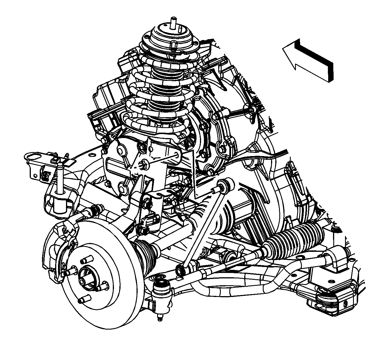

    Object Number: 1720288  Size: SH
  47. Install the left and right stabilizer links to the struts.
  48. Install the stabilizer link to strut nuts.
  49. Tighten
    Tighten the nut to 65 N·m (48 lb ft).

  50. Lower the vehicle.

  51. Object Number: 1720383  Size: SH
  52. If equipped with a automatic transaxle, install the oil cooler lines to the transaxle.
  53. Install the oil cooler line nut.
  54. Tighten
    Tighten the nut to 7 N·m (62 lb in).
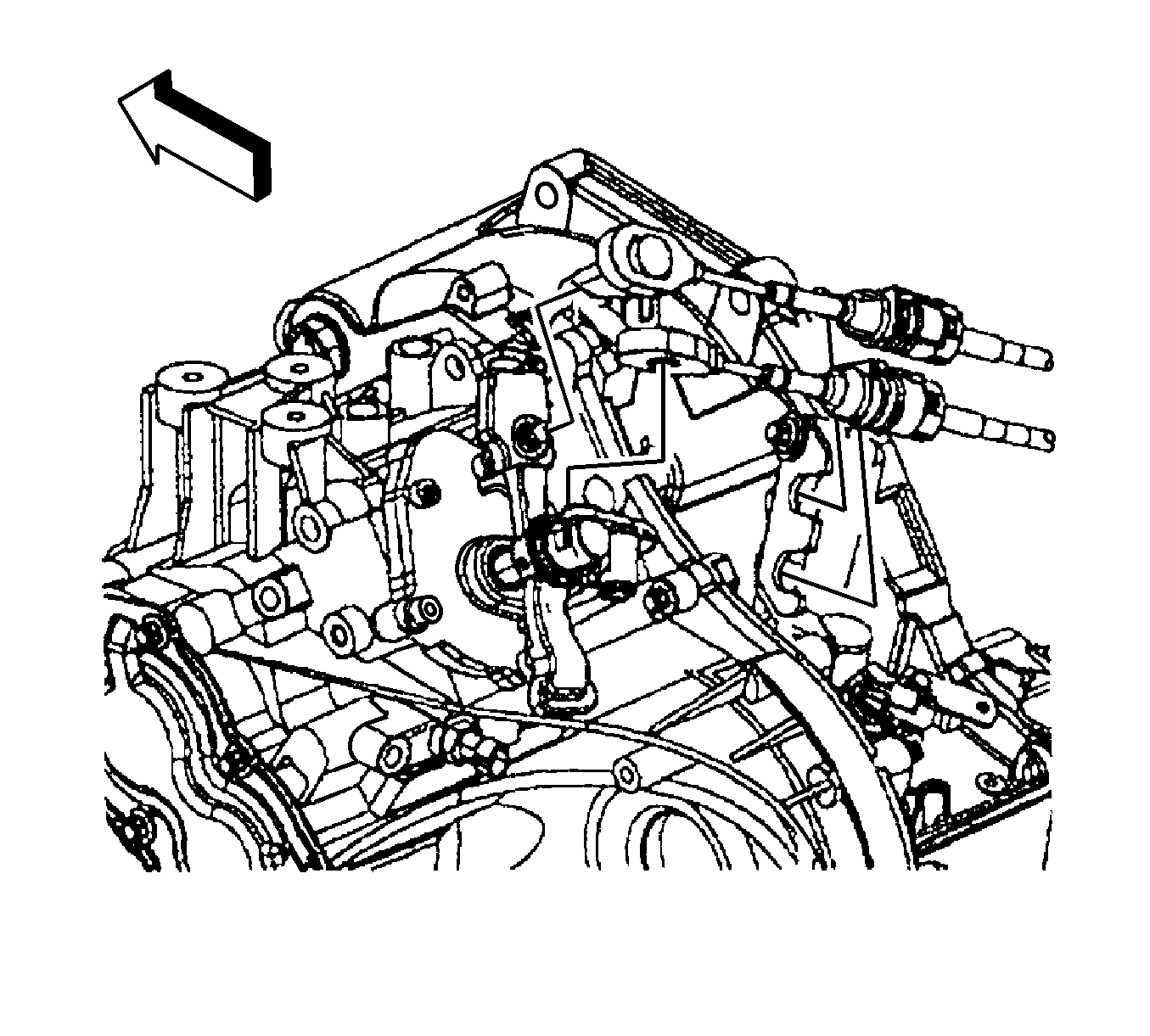

    Object Number: 1625583  Size: SH
  55. If equipped with a manual transaxle, install the range selector and shift lever cables to the transaxle bracket.
  56. Install the range selector and shift lever cables to the transaxle levers.
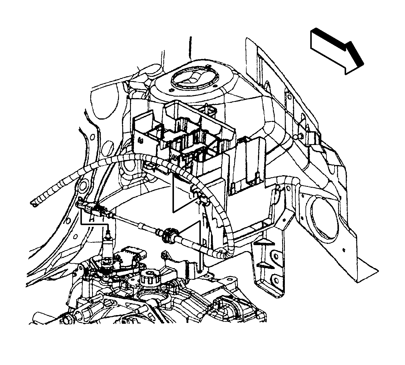
  57. Object Number: 1625581  Size: SH
  58. If equipped with a automatic transaxle, install the range selector lever cable to the transaxle bracket.
  59. Connect the range selector lever cable to the transaxle lever.
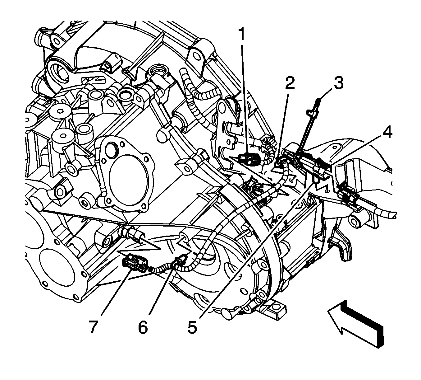
  60. Object Number: 1625489  Size: SH
  61. Gather all engine harness branches and position the harness over the engine.
  62. If equipped with a manual transaxle perform the following steps, install the engine harness clip (6) to the transaxle.
  63. Connect the engine harness electrical connector (7) to the back up lamp switch.
  64. Connect the engine harness electrical connector (4) to the HO2S.
  65. Install the engine harness electrical connector clip (5) to the transaxle rear mount bracket.
  66. Install the engine harness clip (2) to the transaxle.
  67. Install the CPA retainer (3).
  68. Connect the engine harness electrical connector (1) to the VSS.
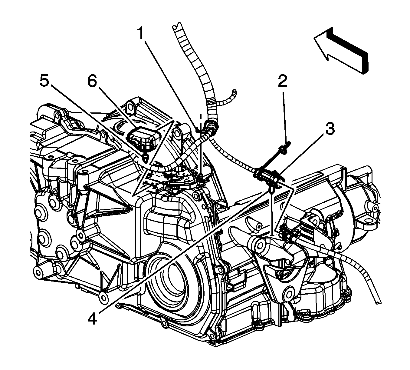
  69. Object Number: 1625487  Size: SH
  70. If equipped with a automatic transaxle perform the following steps, connect the engine harness electrical connector (3) to the HO2S.
  71. Install the CPA retainer (2).
  72. Install the engine harness electrical connector clip (4) to the transaxle rear mount bracket.
  73. Install the engine harness clip (1) to the transaxle stud.
  74. Connect the engine harness electrical connector (6) to the park neutral position switch.
  75. Install the CPA retainer (5).

  76. Object Number: 1625486  Size: SH
  77. If equipped with a manual transaxle perform the following steps, connect the engine harness electrical connector (3) to the HO2S.
  78. Install the CPA retainer (2).
  79. Connect the ECT sensor electrical connector (1).
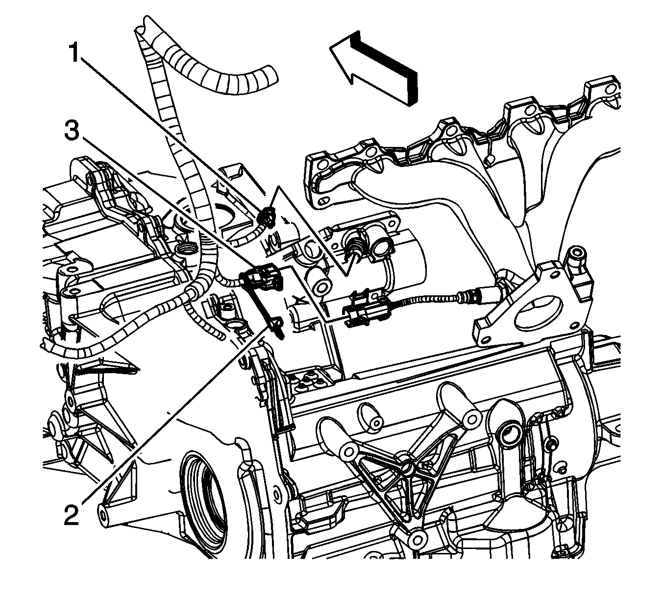
  80. Object Number: 1625483  Size: SH
  81. If equipped with a automatic transaxle perform the following steps, connect the engine harness electrical connector (3) to the HO2S.
  82. Install the CPA retainer (2).
  83. Connect the ECT sensor electrical connector (1).
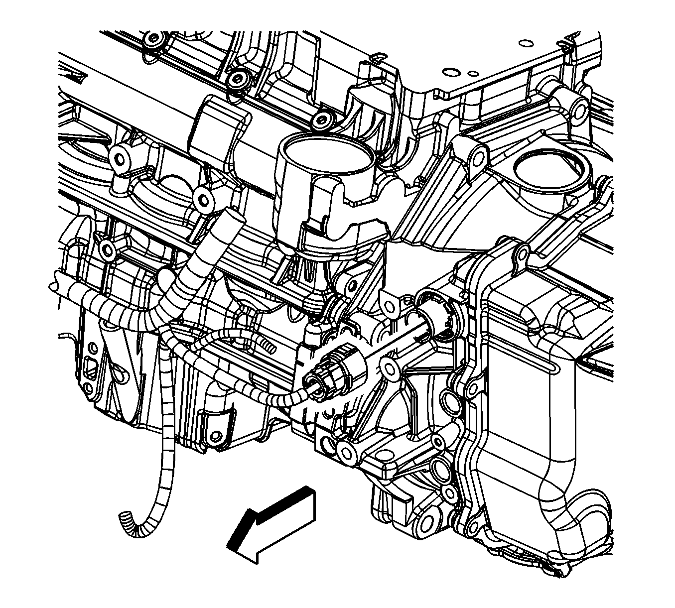
  84. Object Number: 1625479  Size: SH
  85. If equipped with a automatic transaxle, connect the engine harness to the transaxle.
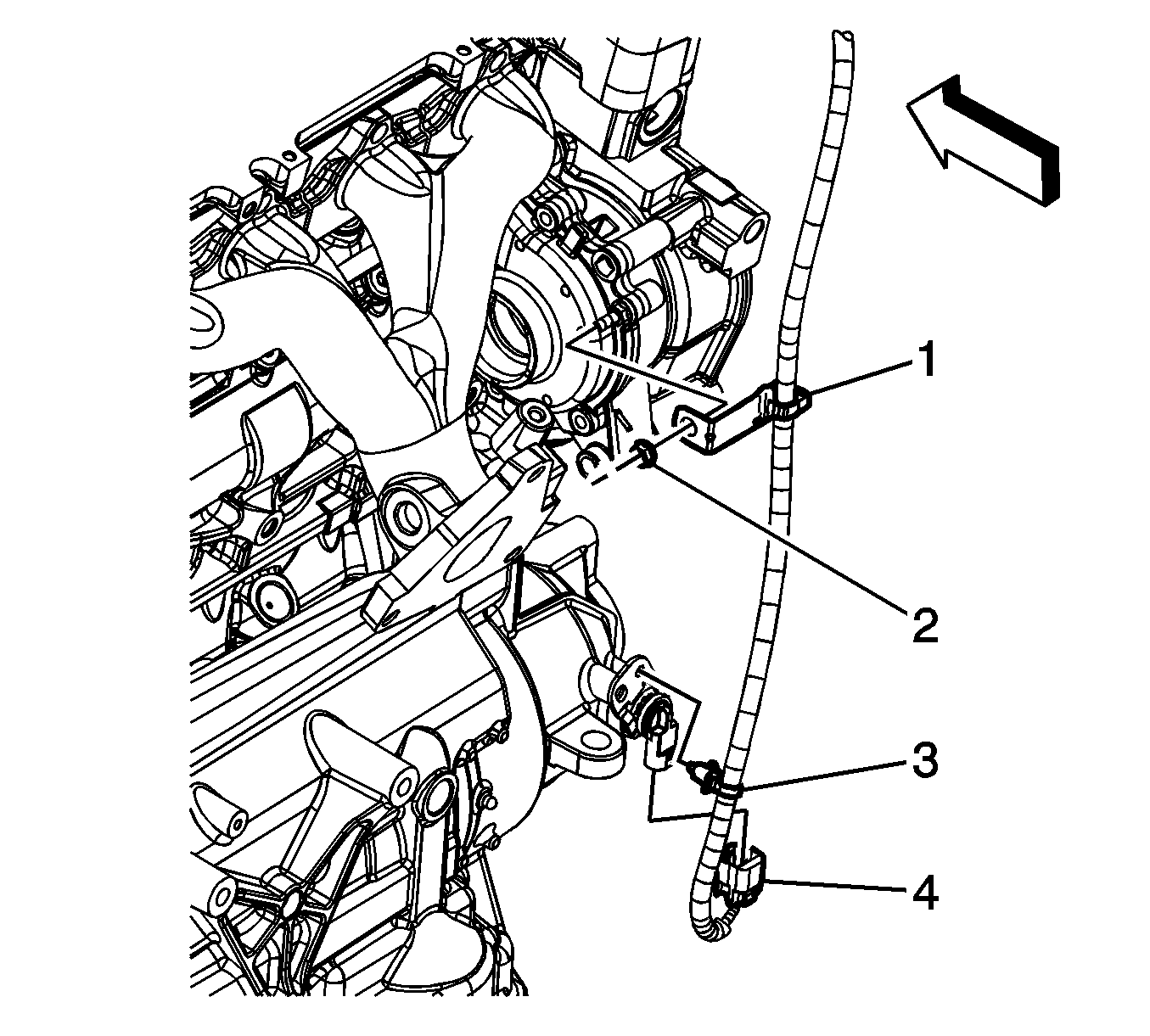
  86. Object Number: 1625484  Size: SH
  87. If equipped with a automatic transaxle, install the engine harness clip (3) to the speed sensor.
  88. Connect the VSS electrical connector (4).
  89. Install the engine harness clip (1) to the stud.
  90. Install the engine harness clip nut (2) to the engine stud.
  91. Tighten
    Tighten the nut to 10 N·m (89 lb in).
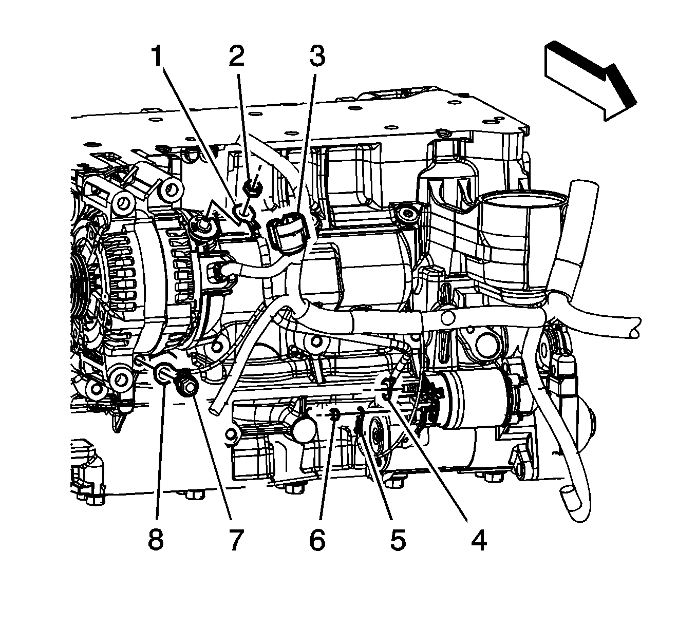

    Object Number: 1625472  Size: SH
  92. Install the engine harness lead terminal (1) to the generator.
  93. Install the generator nut (2).
  94. Tighten
    Tighten the nut to 20 N·m (14 lb ft).

  95. Raise and support the vehicle.
  96. Install the engine harness ground (8) to the engine block.
  97. Install the engine harness ground bolt (7).
  98. Tighten
    Tighten the bolt to 25 N·m (18 lb ft).
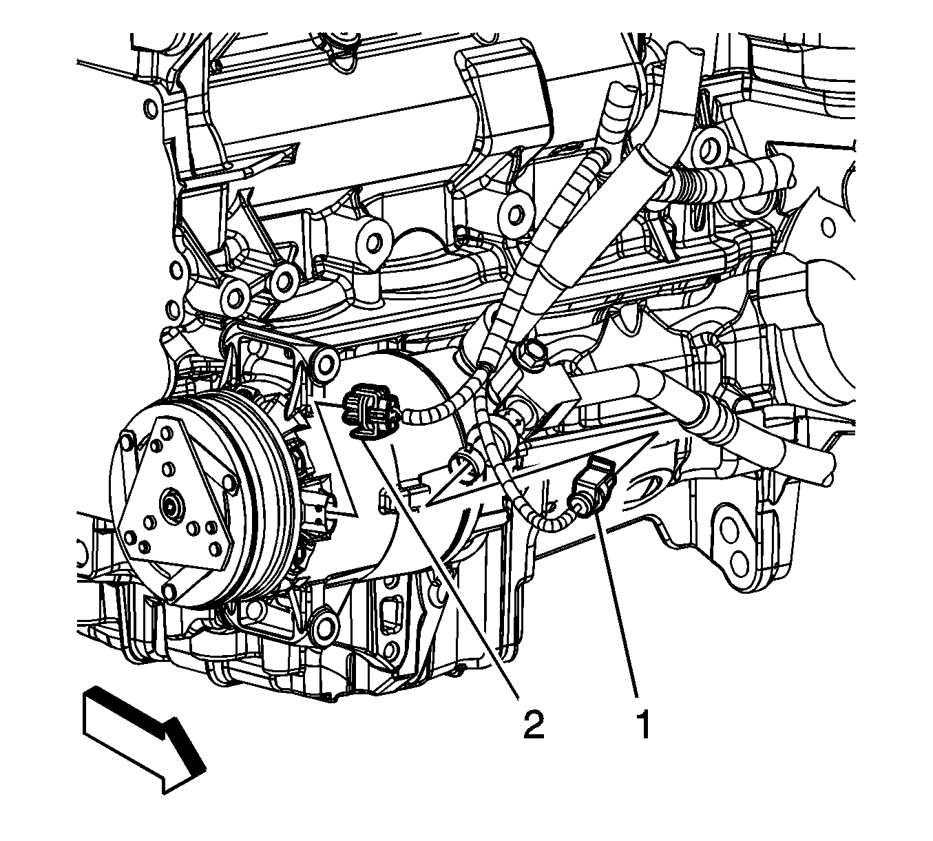

    Object Number: 1625475  Size: SH
  99. Unsecure the A/C compressor and position to the engine block. Install the A/C compressor bolts.
  100. Tighten
    Tighten the bolts to 22 N·m (16 lb ft).

  101. Connect the A/C compressor electrical connector (2).
  102. Connect the A/C pressure switch electrical connector (1).
  103. Raise and support the vehicle.

  104. Object Number: 1622807  Size: SH
  105. If equipped with a manual transaxle perform the following steps, install the engine harness ground terminal (4) to the stud.
  106. Install the positive/negative cable (3) terminal to the stud.
  107. Install the positive/negative battery cable ground nut (2).
  108. Tighten
    Tighten the nut to 10 N·m (89 lb in).

  109. Connect the following electrical connectors:
  110. • CKP sensor (1)
    • Oil pressure sensor (5)
    • Knock sensor (6)

    Object Number: 1622787  Size: SH
  111. If equipped with a automatic transaxle perform the following steps, install the engine harness ground terminal (3) to the stud.
  112. Install the positive/negative cable (2) terminal to the stud.
  113. Install the positive/negative battery cable ground nut (1).
  114. Tighten
    Tighten the nut to 10 N·m (89 lb in).

  115. Connect the following electrical connectors:
  116. • CKP sensor (4)
    • Oil pressure sensor (5)
    • Knock sensor (6)
  117. Install the starter. Refer to Starter Motor Replacement .
  118. Object Number: 1627740  Size: SH
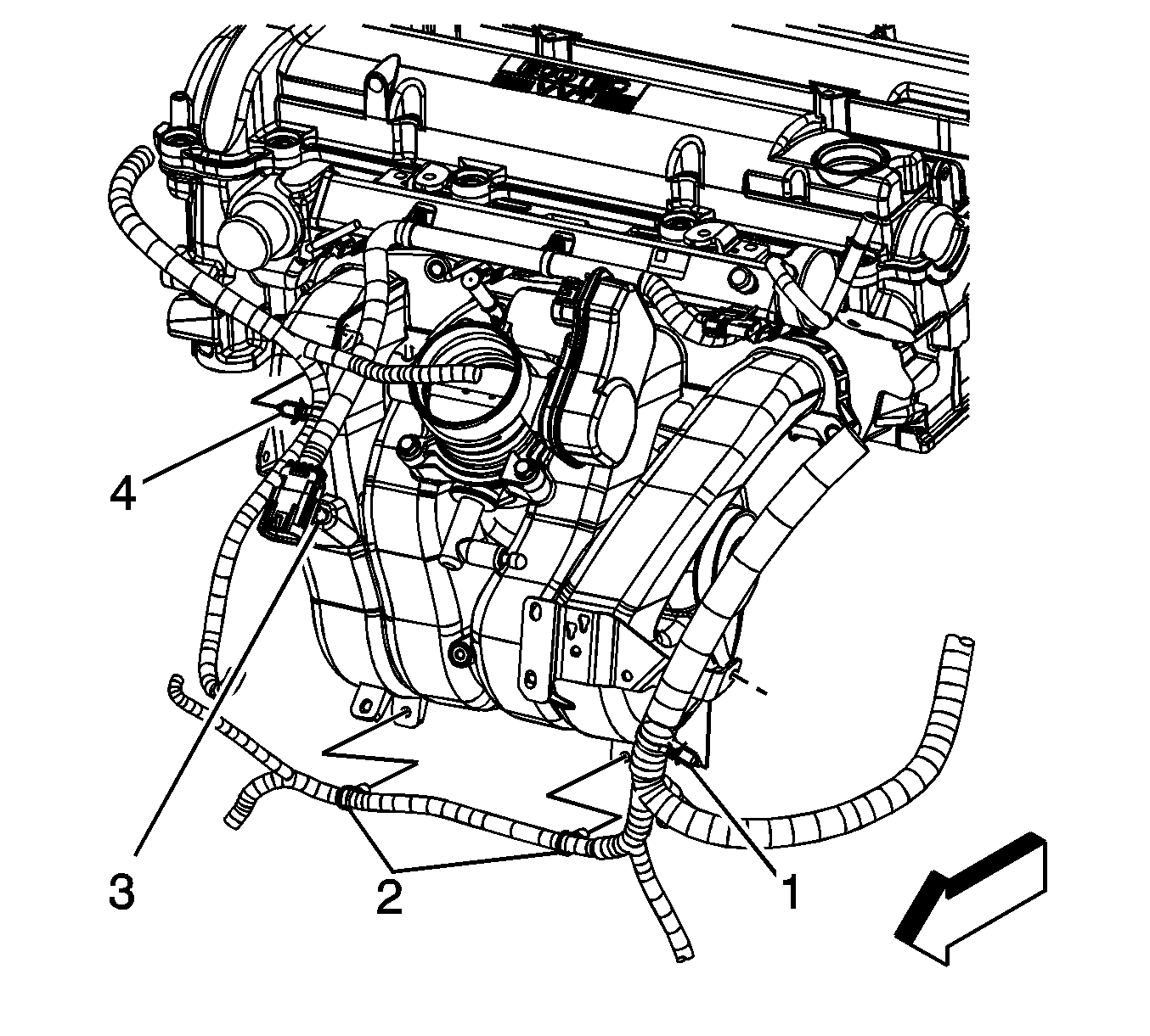
  119. Install the engine harness clips (2, 4) to the intake manifold.
  120. Lower the vehicle.
  121. Install the engine harness clip (1) to the oil level indicator tube bracket.
  122. Object Number: 1625463  Size: SH
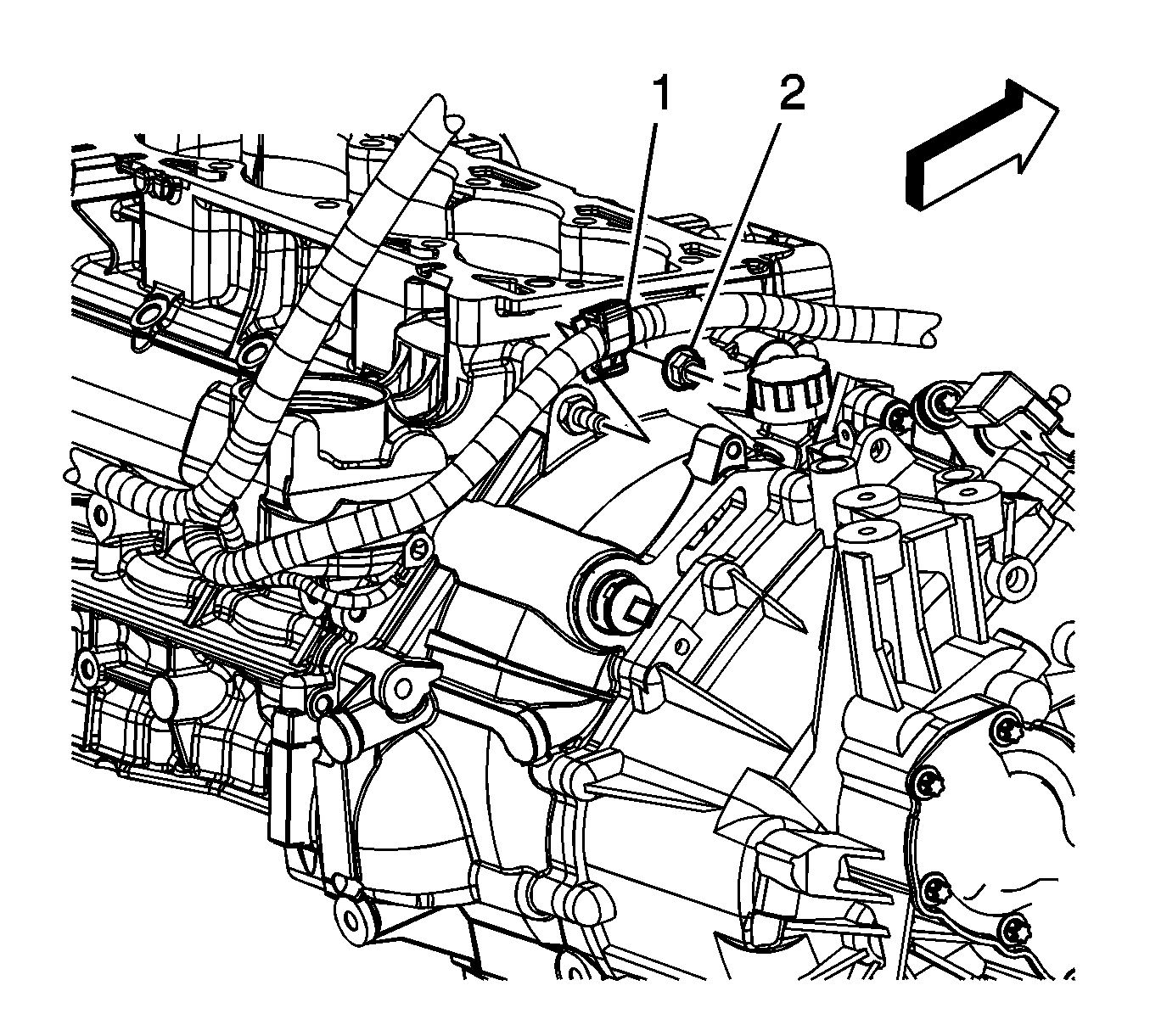
  123. Install the engine harness clip (1) to the transaxle stud.
  124. Install the engine harness clip nut (2).
  125. Tighten
    Tighten the nut to 10 N·m (89 lb in).

    Object Number: 1631141  Size: SH
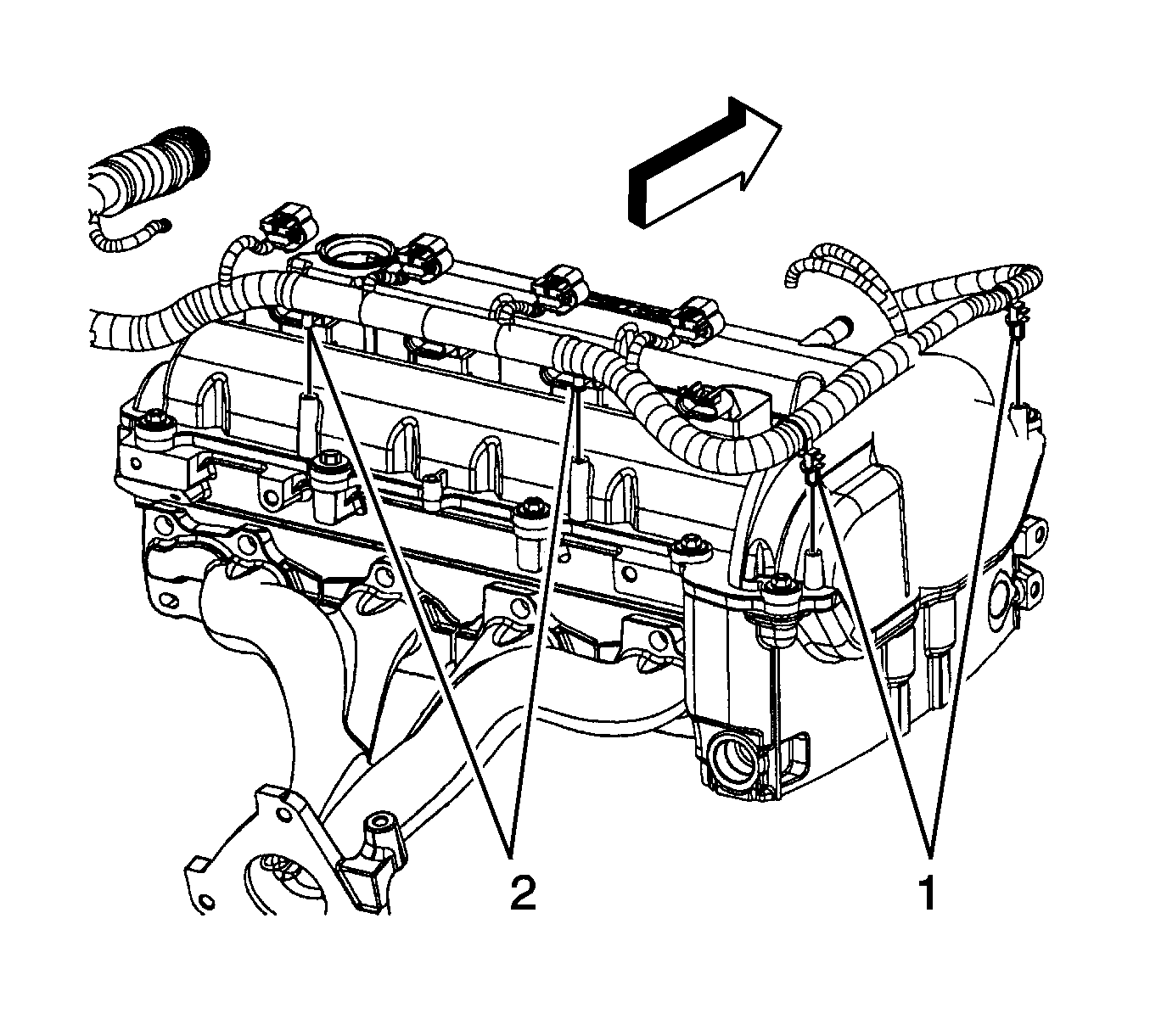
  126. Install the engine harness clips (1, 2) to the camshaft cover.
  127. Object Number: 1628020  Size: SH
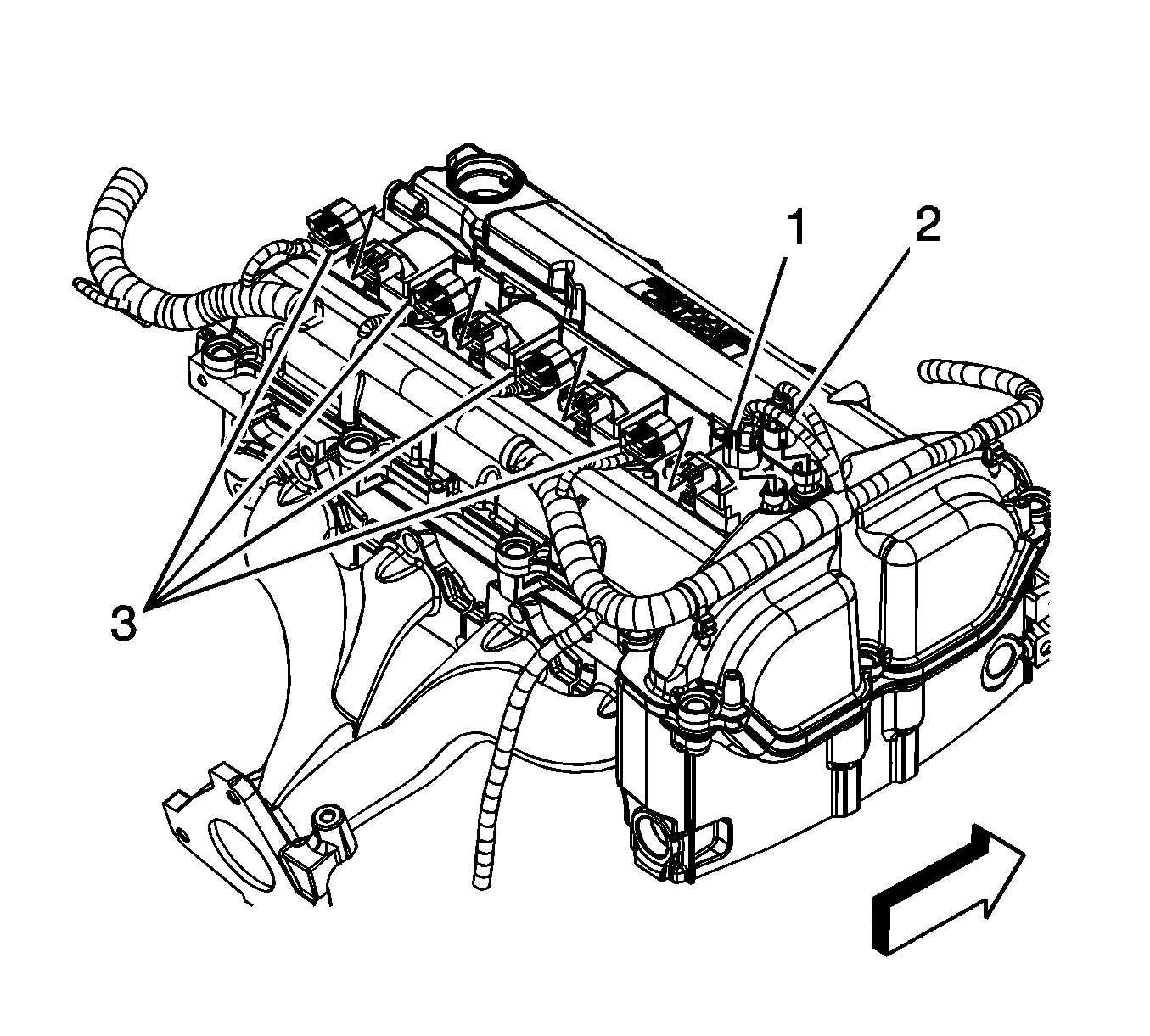
  128. Connect the intake (2) and exhaust (1) camshaft position actuator electrical connectors.
  129. Connect the ignition coils electrical connectors (3).
  130. Object Number: 1623764  Size: SH
  131. Connect the following electrical connectors:
  132. •  TAC (1)
    • MAP sensor
    • Fuel injector harness (2)
    • Generator (3)

    Object Number: 1628035  Size: SH
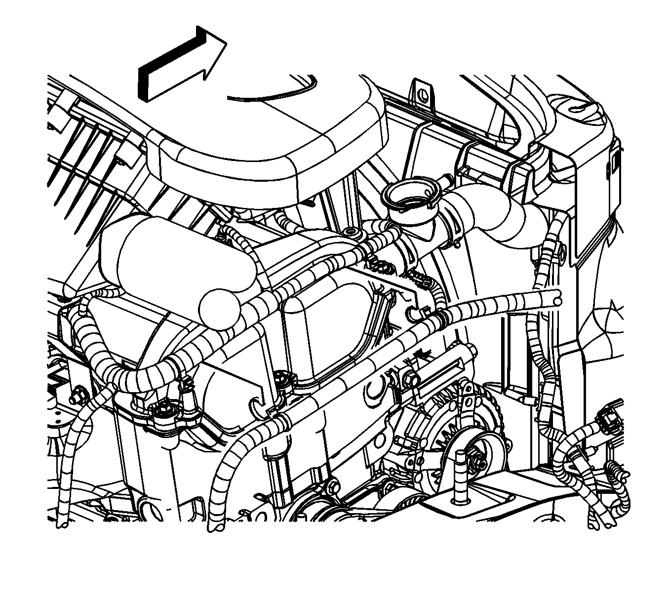
  133. Install the brake booster vacuum hose to the intake manifold.
  134. Position the brake booster vacuum hose clamp at the intake manifold.
  135. Object Number: 1625676  Size: SH
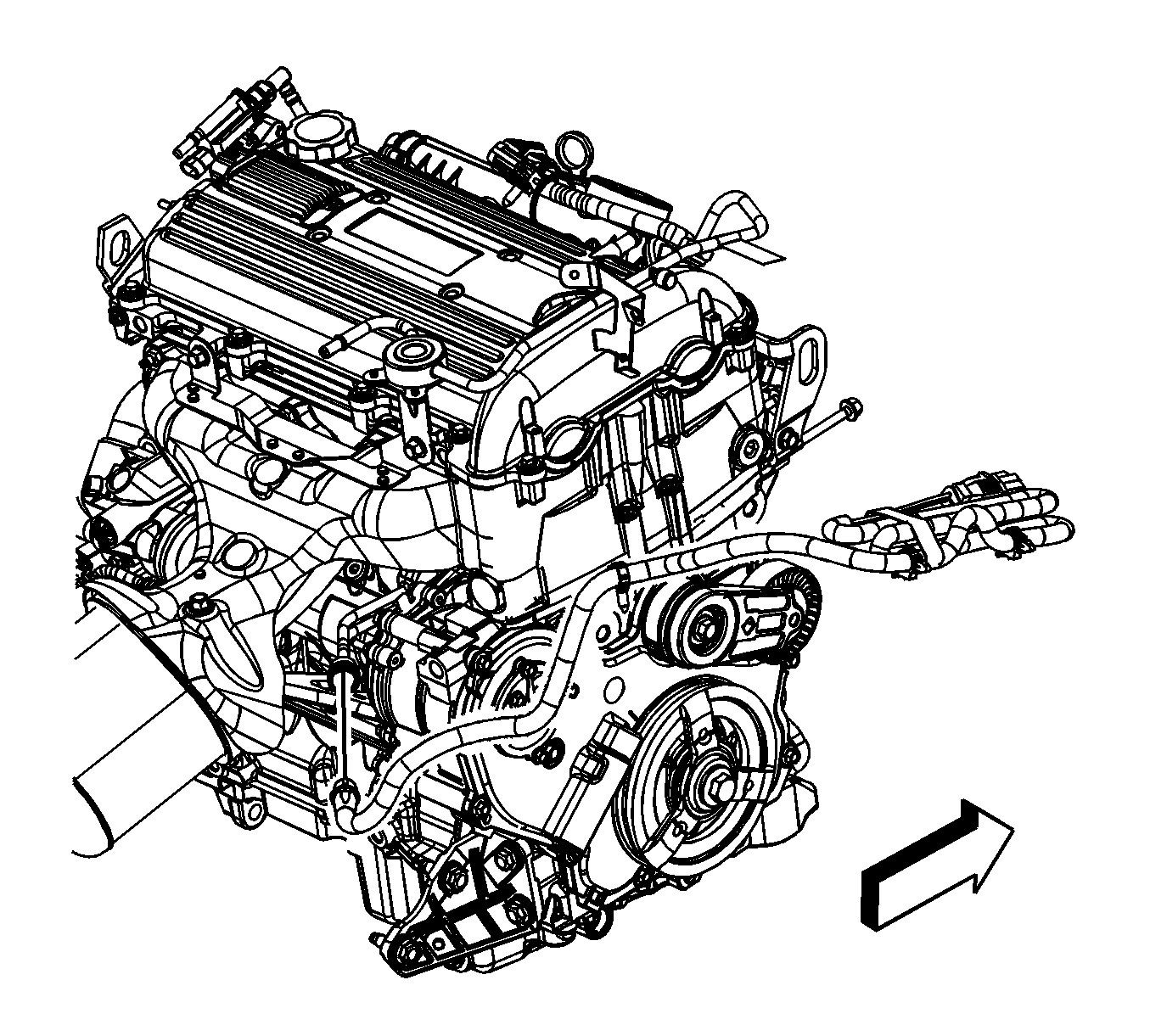
  136. Position the engine coolant heater cord, if equipped.
  137. Install the engine coolant heater cord straps to the engine harness, if equipped.
  138. Object Number: 1625669  Size: SH
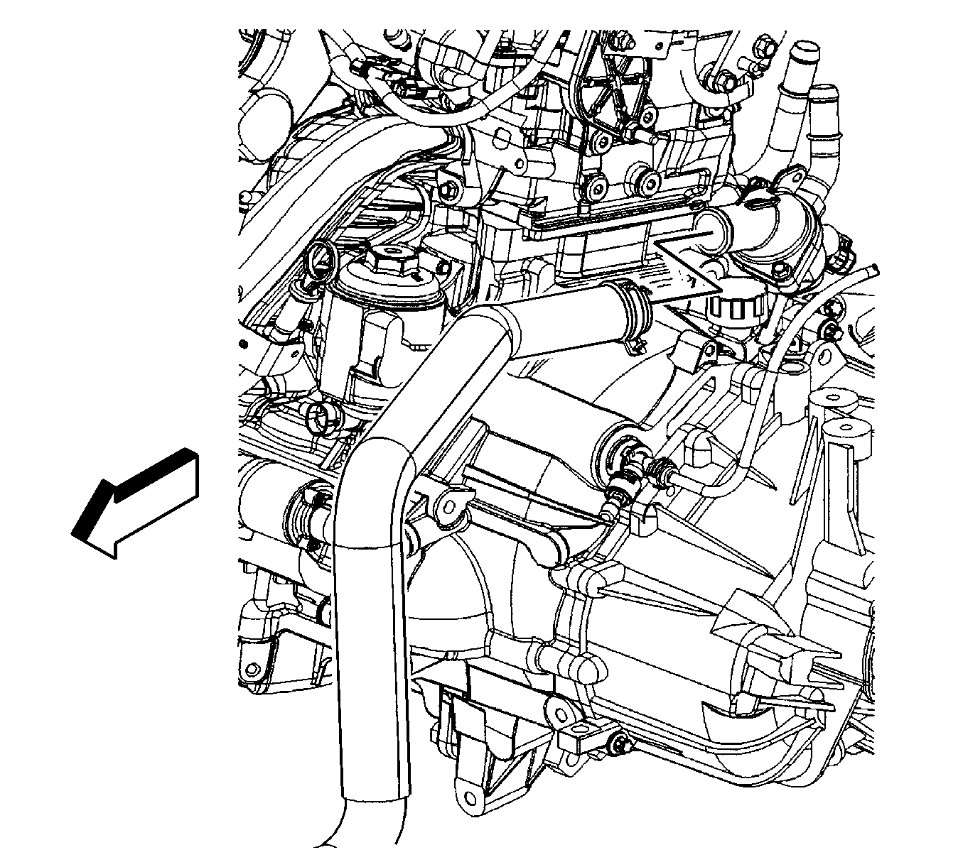
  139. Connect the engine coolant heater cord, if equipped.
  140. Object Number: 1713958  Size: SH
  141. If the vehicle is not equipped with a engine oil cooler, install the radiator outlet hose to the engine.
  142. Position the radiator outlet hose clamp at the engine.
  143. Object Number: 1631170  Size: SH
  144. If the vehicle is equipped with a engine oil cooler perform the following steps, install the radiator outlet hose to the oil cooler.
  145. Install the radiator outlet hose to the water outlet.
  146. Position the radiator outlet hose clamp (2) at the oil cooler.
  147. Position the radiator outlet hose clamp (1) at the water outlet.
  148. Object Number: 1625419  Size: SH
  149. Install the heater inlet and outlet hoses to the thermostat housing.
  150. Position the heater inlet and outlet hose clamps at the thermostat housing.
  151. Object Number: 1639712  Size: SH
  152. Connect the intake (2) and exhaust (1) CMP sensor electrical connectors.
  153. Object Number: 1625460  Size: SH
  154. Install the engine harness clip (1) to the EVAP purge solenoid bracket.
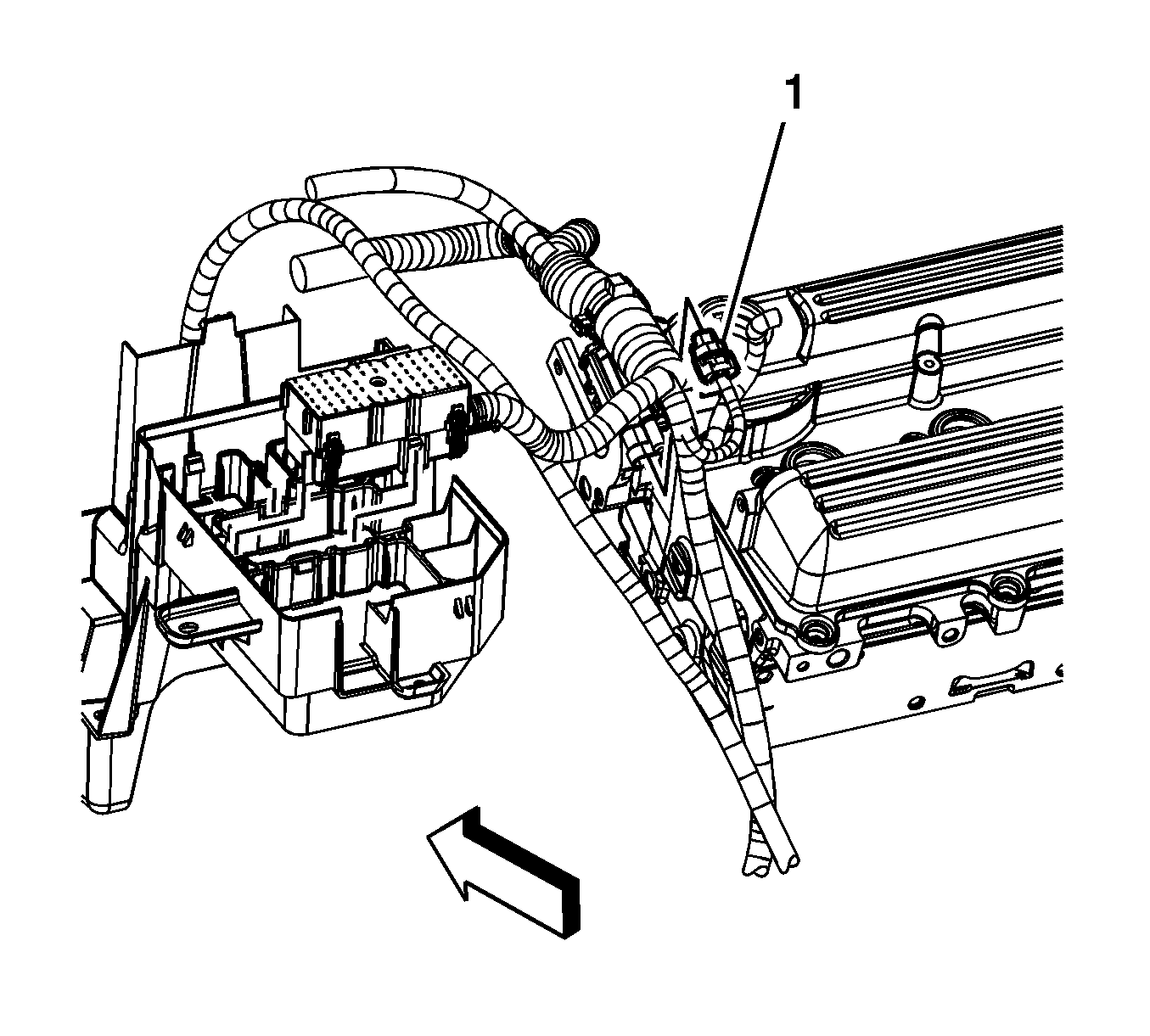
  155. Object Number: 1625517  Size: SH
  156. Connect the EVAP purge solenoid electrical connector (1).
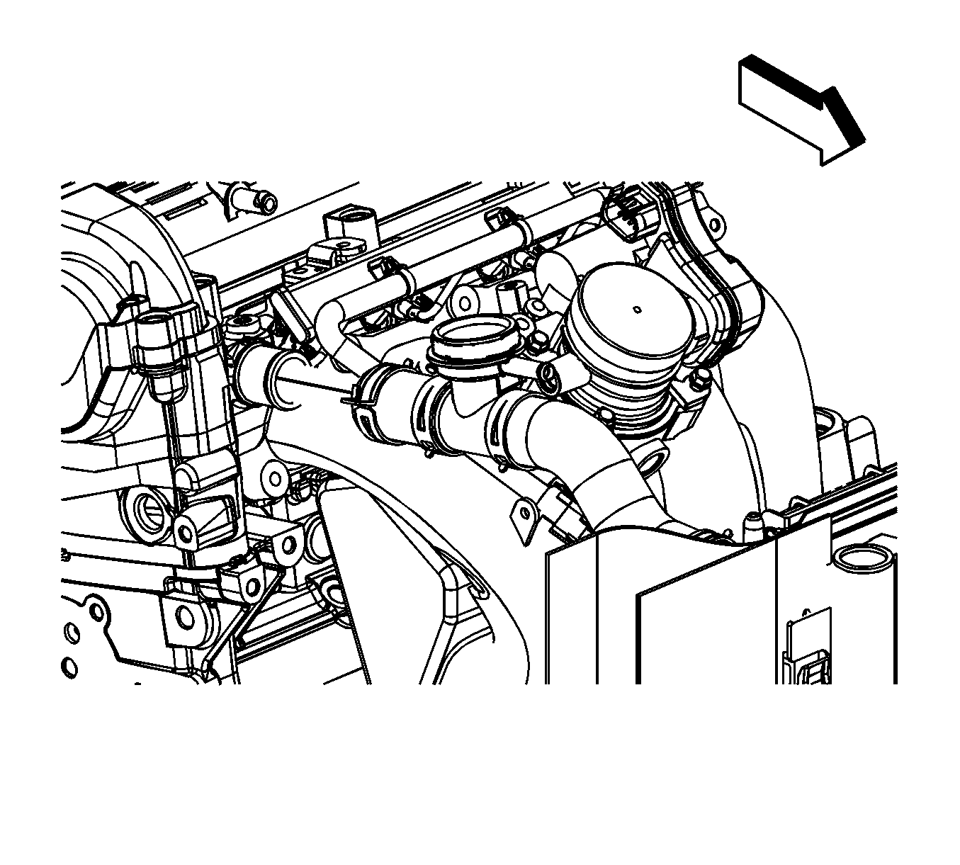
  157. Object Number: 1625418  Size: SH
  158. Install the radiator inlet hose to the engine.
  159. Position the radiator inlet hose clamp at the engine.
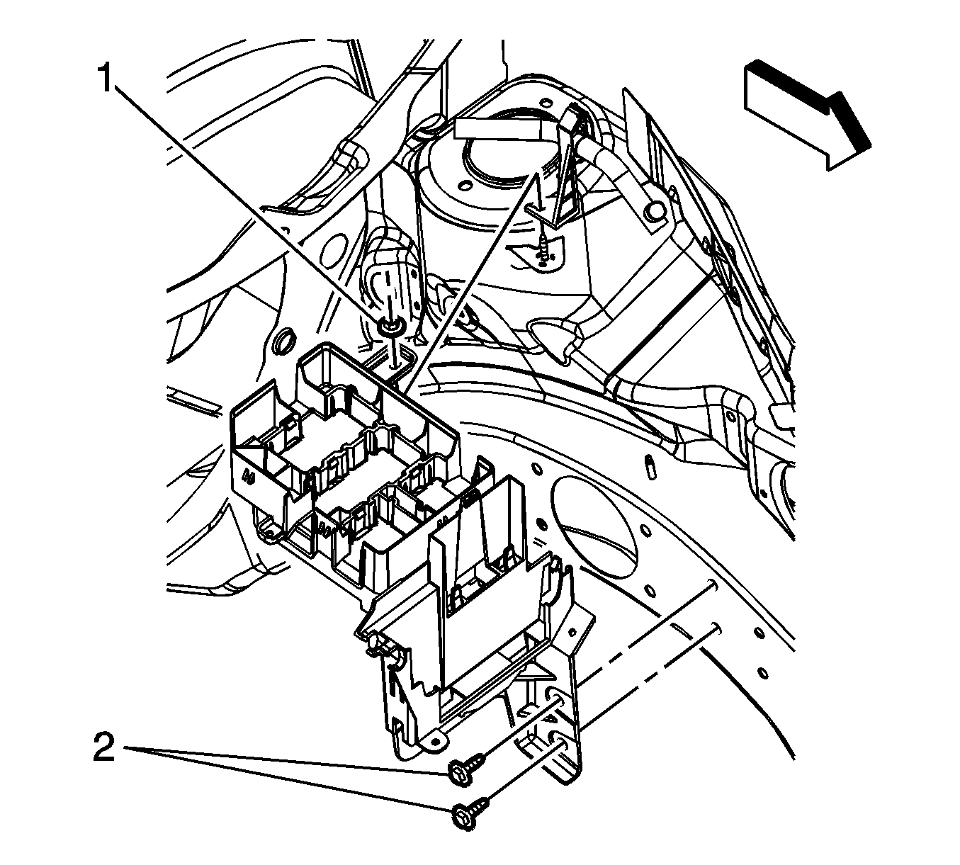
  160. Object Number: 1720487  Size: SH
  161. Position and install the ECM bracket to the studs.
  162. Install the ECM bracket nuts (1) and bolts (2).
  163. Tighten

        • Tighten the bolts to 25 N·m (18 lb ft).
        • Tighten the nuts to 10 N·m (89 lb in).

    Object Number: 1631516  Size: SH
  164. Install the positive battery cable terminal (1) to the junction block stud.
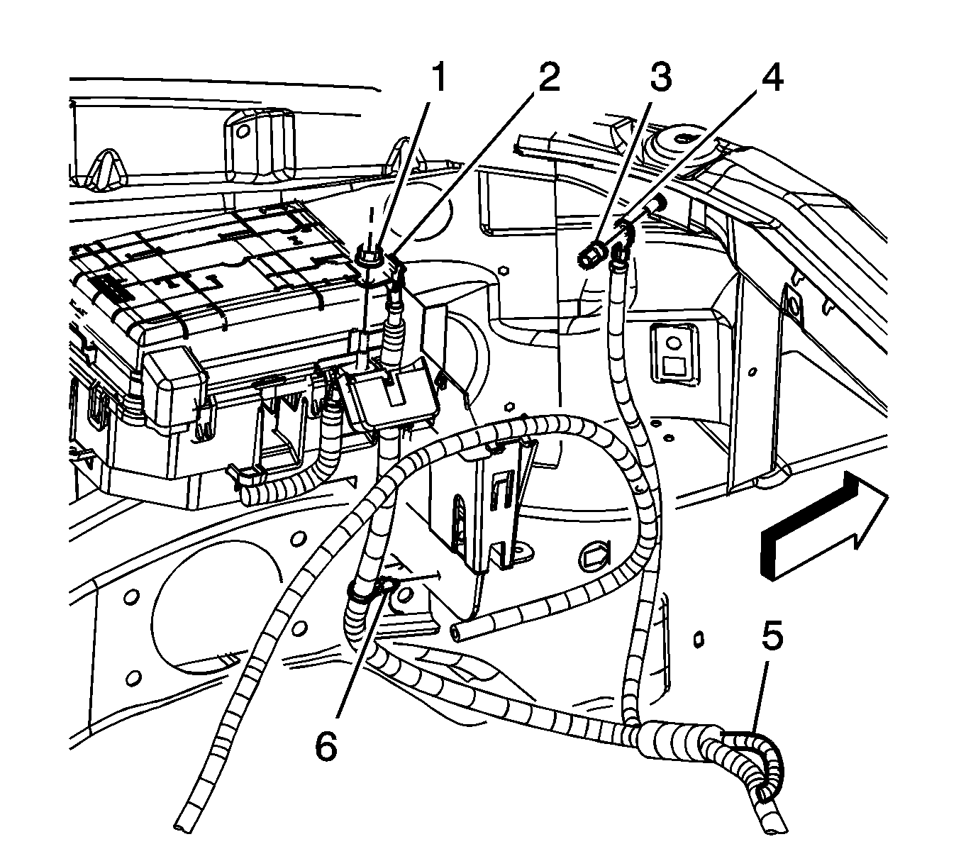
  165. Object Number: 1631518  Size: SH
  166. Install the positive/negative battery cable terminal (2) to the stud.
  167. Install the junction block terminal nut (1).
  168. Tighten
    Tighten the nut to 15 N·m (11 lb ft).

  169. Close the junction block terminal cover.
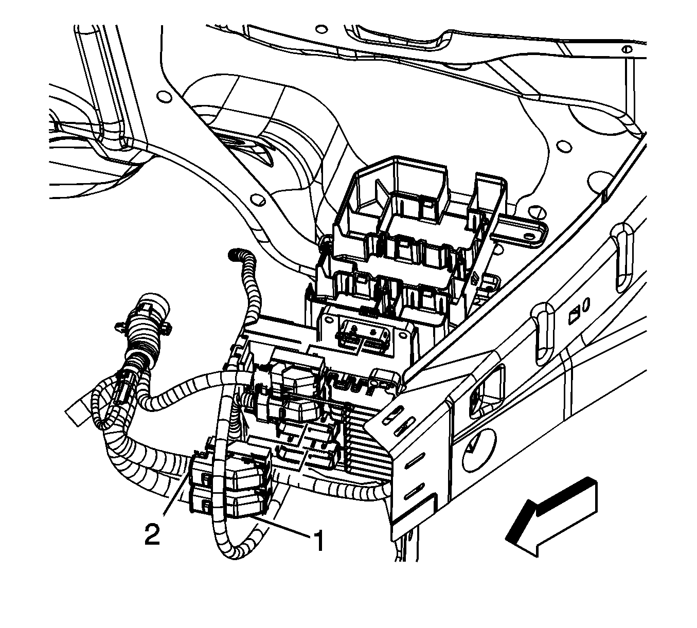
  170. Object Number: 1639228  Size: SH
  171. Connect the engine harness electrical connectors (1, 2) to the ECM.
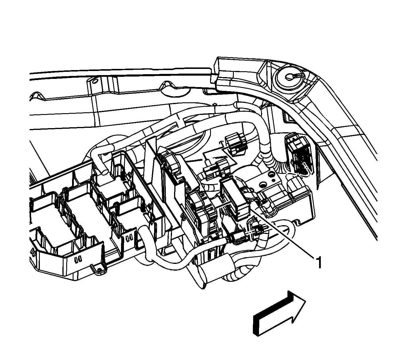
  172. Object Number: 1639226  Size: SH
  173. Connect the body harness electrical connector (1) to the ECM.
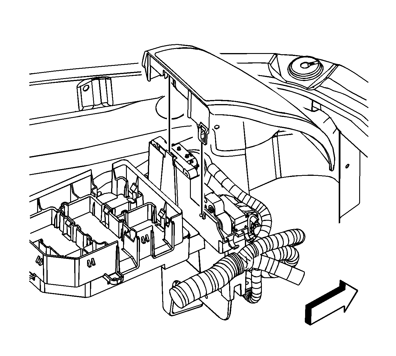
  174. Object Number: 1631889  Size: SH
  175. Install the ECM/TCM cover.
  176. Raise the vehicle.

  177. Object Number: 1625478  Size: SH
  178. Connect the cooling fan electrical connector.
  179. Install the catalytic converter. Refer to Catalytic Converter Replacement .
  180. Install the left side engine splash shield. Refer to Engine Splash Shield Replacement .
  181. Install the engine drive belt. Refer to Drive Belt Replacement .
  182. Install the windshield washer solvent reservoir. Refer to Windshield Washer Solvent Container Replacement .
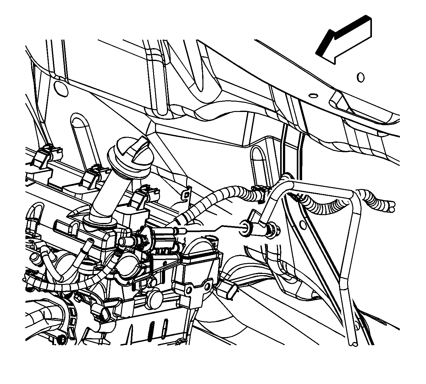
  183. Object Number: 1625606  Size: SH
  184. Connect the EVAP line to the EVAP purge solenoid. Refer to Plastic Collar Quick Connect Fitting Service .
  185. Object Number: 1625417  Size: SH
  186. Connect the fuel feed line to the fuel rail. Refer to Metal Collar Quick Connect Fitting Service
  187. Connect the negative battery cable. Refer to Battery Negative Cable Disconnection and Connection .
  188. Perform the engine prelubing procedure. Refer to Engine Prelubing .
  189. Fill the cooling system. Refer to Cooling System Draining and Filling .
  190. Check the automatic transaxle fluid, if equipped, add as needed. Refer to Transmission Fluid Check .
  191. Check the manual transaxle fluid, if equipped, add as needed. Refer to Transmission Fluid Check .
  192. Install the air cleaner assembly. Refer to Air Cleaner Assembly Replacement .
  193. Close the hood.
  194. Check the front alignment. Refer to Wheel Alignment Measurement .