Tools Required
| • | J 38613-A Camshaft Timing Clamps |
| • | J 38619 Camshaft and Intermediate Shaft Seal Installer |
Removal Procedure
- Remove the camshaft carrier. Refer to Camshaft Carrier Replacement .
- Remove the lifters. Refer to Valve Lifter Replacement .
- Remove the oil from the camshaft hold down tool hole in the camshaft carrier.
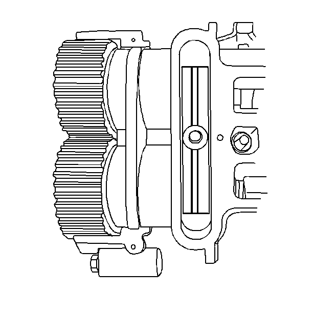
- Install the J 38613-A .
- Remove the camshaft sprockets. Refer to Camshaft Driven Sprocket Replacement .
- Remove the thrust plate cover and the thrust plate gasket.
- Remove the thrust plate bolts.
- Remove the thrust plate.
- Remove the J 38613-A .
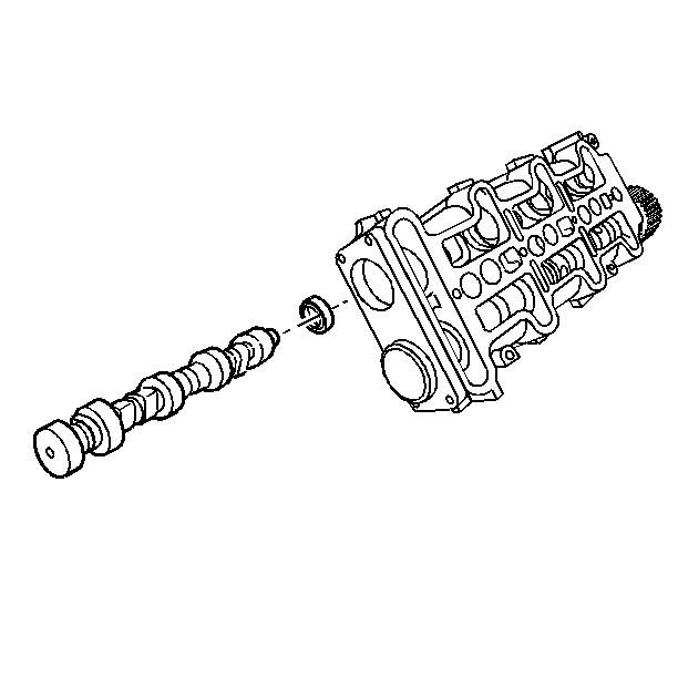
- Carefully remove the camshaft out of the back of the camshaft carrier.
- Remove the camshaft oil seal. Pry out the oil seal with a screwdriver or suitable tool. Take care not to damage the aluminum surfaces around the seal.
- Inspect the camshaft for wear or deformation. Replace as necessary.
- Inspect the camshaft lobes for wear.
- Inspect the nose of the camshaft for brinelling from the lock ring. Pressure marks are acceptable. Grooves on the camshaft are not acceptable and the camshaft must be replaced.
- Inspect the carrier for scratches and/or burrs. Check the surface around the seal.

Notice: Use the correct fastener in the correct location. Replacement fasteners must be the correct part number for that application. Fasteners requiring replacement or fasteners requiring the use of thread locking compound or sealant are identified in the service procedure. Do not use paints, lubricants, or corrosion inhibitors on fasteners or fastener joint surfaces unless specified. These coatings affect fastener torque and joint clamping force and may damage the fastener. Use the correct tightening sequence and specifications when installing fasteners in order to avoid damage to parts and systems.
Tighten
Tighten the J 38613-A
to
30 N·m (22 lb ft).

Notice: All camshaft journals are the same diameter, so care must be used in removing or installing the camshaft to avoid damage to the camshaft bearings.
Installation Procedure
- Install the oil seal with the J 38619 .
- Install the camshaft to the carrier. Do not damage or distort the oil seal.
- Install the thrust plate. Point the arrow on the thrust plate up.
- Install the thrust plate bolts.
- Install the thrust plate gasket and the thrust plate cover.
- Install the lifters. Refer to Valve Lifter Replacement .
- Install the camshaft carrier. Refer to Camshaft Carrier Replacement .
- Remove the oil from the camshaft hold down tool hole in the camshaft carrier.
- Install the J 38613-A .
- Install the camshaft driven sprocket. Refer to Camshaft Driven Sprocket Replacement .

Important: Coat the seal, and the camshaft lobes and journals with engine oil supplement (EOS), GM P/N 1052367 or equivalent before installation.
Notice: Use the correct fastener in the correct location. Replacement fasteners must be the correct part number for that application. Fasteners requiring replacement or fasteners requiring the use of thread locking compound or sealant are identified in the service procedure. Do not use paints, lubricants, or corrosion inhibitors on fasteners or fastener joint surfaces unless specified. These coatings affect fastener torque and joint clamping force and may damage the fastener. Use the correct tightening sequence and specifications when installing fasteners in order to avoid damage to parts and systems.
Tighten
Tighten the thrust plate bolts to 10 N·m (89 lb in).
Tighten
Tighten the thrust plate cover bolts to 10 N·m (89 lb in).
Tighten
Tighten the J 38613-A
to
30 N·m (22 lb ft).
