Notice: In order to prevent internal damage to the PCM, the ignition must be OFF when disconnecting or reconnecting the PCM connector.
Service of the PCM should normally consist of either replacement of the PCM or EEPROM re-programming.
If the diagnostic procedures call for the PCM to be replaced, the PCM should be checked first to see if it is the correct part. DTC P0601 indicates the EEPROM programming has malfunctioned. When DTC P0601 is obtained, re-program the EEPROM.
The ignition should be OFF for at least 10 seconds before disconnecting power to the PCM so the IAC valve has time to move to the engine OFF position.
Removal Procedure
Important: Turn the ignition switch OFF to prevent internal PCM damage when disconnecting or reconnecting power to the PCM (for example, battery cable, PCM pigtail, PCM fuse, jumper cables, etc.). The ignition switch should be OFF for at least 10 seconds before disconnecting power to the PCM so the IAC valve has time to move to the engine OFF position.
- Disconnect the negative battery cable.
- Remove the LH hush panel.
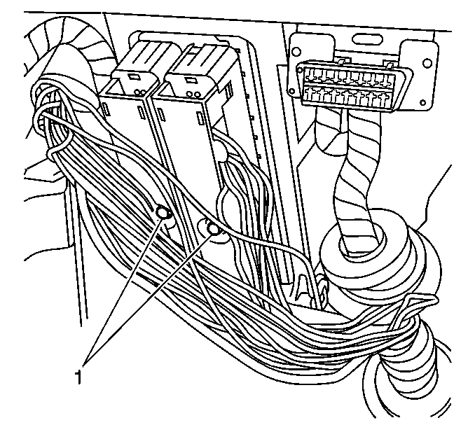
- Loosen the PCM electrical connectors screws (1).
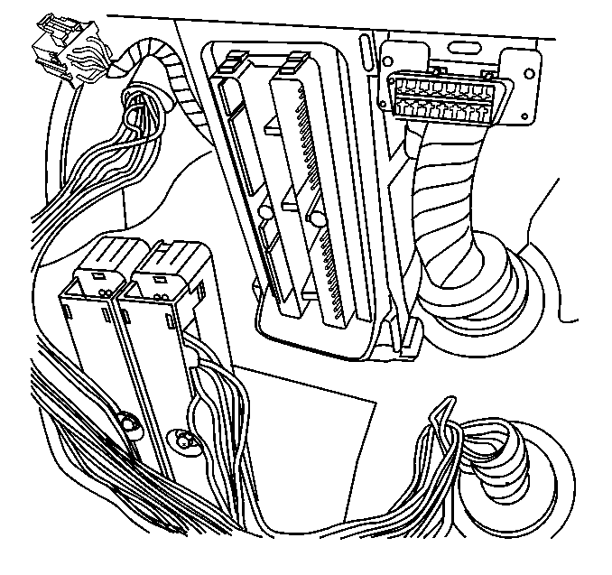
- Disconnect the PCM electrical connectors.
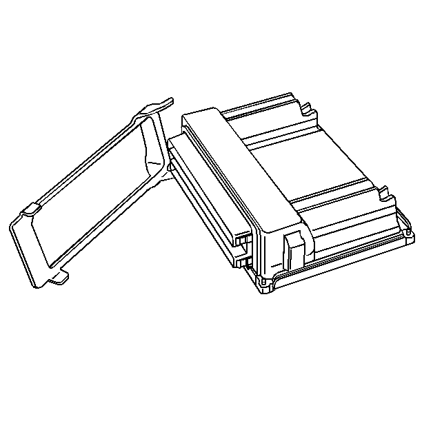
- Remove the PCM Retainer.
- Slide the PCM from the PCM bracket.
Caution: Unless directed otherwise, the ignition and start switch must be in the OFF or LOCK position, and all electrical loads must be OFF before servicing any electrical component. Disconnect the negative battery cable to prevent an electrical spark should a tool or equipment come in contact with an exposed electrical terminal. Failure to follow these precautions may result in personal injury and/or damage to the vehicle or its components.


Notice: Do not touch the PCM connector pins or soldered components on the circuit board in order to prevent possible electrostatic discharge (ESD) damage. Do not remove the integrated circuit boards from the carrier.

Installation Procedure
Remove the new PCM from its packaging and check the service number to make sure it is the same number or updated number as the malfunctioning PCM.
- Slide the PCM into the PCM bracket.
- Install the PCM Retainer.
- Install the PCM electrical connectors.
- Tighten the PCM connector screws (1).
- Install the LH hush panel.
- Connect the negative battery cable.
- Reprogram the PCM and perform the Crankshaft Position System Variation Learning Procedure .

Notice: Do not touch the PCM connector pins or soldered components on the circuit board in order to prevent possible electrostatic discharge (ESD) damage. Do not remove the integrated circuit boards from the carrier.


Crankshaft Position System Variation Learning Procedure
Important: A Crankshaft Position System Variation Learning Procedure must be performed any time a change is made to the crankshaft sensor to crankshaft relationship. Changing the crank sensor to crankshaft relationship will not allow the PCM to detect misfire at all speeds and loads accurately. Resulting in a possible false misfire DTC being set.
Removing a part for inspection and then reinstalling the same part is considered a disturbance. A false DTC P0300 could be set if this procedure is not performed.
The learn procedure is required after the following service procedures have been performed, regardless of whether or not DTC P1336 is set:
| • | PCM replacement or reprogrammed. |
| • | Engine replacement. |
| • | Crankshaft replacement. |
| • | Crankshaft position sensor replacement. |
| • | Any engine repair(s) which disturbs the crankshaft/harmonic balancer to the crankshaft position sensor relationship. |
Caution: Before performing the Crankshaft Position System Variation Learning Procedure always set the vehicle parking brake and block the drive wheels in order to prevent personal injury. Release the throttle immediately when the engine starts to decelerate in order to eliminate over revving the engine. Once the learn procedure is completed, the control module will return engine control to the operator and the engine will respond to the throttle position.
Important: The battery must be fully charged and in good condition. The scan tool connection at the DLC is clean and tight before starting the Crankshaft Position System Variation Learning Procedure.
- Block the drive wheels and set the vehicle parking brake.
- Put the vehicle in Park or Neutral.
- Turn all the accessories OFF.
- Install a scan tool.
- Start and run the engine until it is at normal operating temperature 85°C (185°F).
- With the engine still running, enable the Crankshaft Position System Variation Learning Procedure with the scan tool.
- Press and hold the brake pedal firmly and raise the engine speed to the specified value, RELEASING the throttle as soon as the engine cuts out.
- Verify with the scan tool that the crankshaft variation has been learned.
Perform this procedure up to 10 times. If the PCM will not learn the variation, a DTC P1336 should be set. Refer to the DTC P1336 Crankshaft Position (CKP) System Variation Not Learned for diagnosis.
Password Learn Procedure
In order for a theft deterrent vehicle to run, a password is communicated between the Instrument Panel Cluster (IPC) and the PCM. If a PCM is replaced, the new PCM needs to learn the correct password of the vehicle. When the new PCM is installed, the EEPROM calibration is flashed into the new PCM and the vehicle will learn the new password upon initial ignition ON. If the IPC is replaced, the PCM needs to learn the new password from the IPC. The password learn procedure is as follows:
- Attempt to start vehicle, then leave the ignition ON. The THEFT SYSTEM telltale will flash for 10 minutes.
- When the THEFT SYSTEM telltale stops flashing, start the vehicle. Once the vehicle is running, the password is learned.
