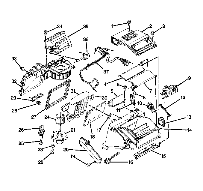
The vacuum tank is located on top of the HVAC module. During heavy acceleration, the vacuum supply from the intake manifold drops. Under load conditions the following actions occur:
| • | A check valve in the vacuum tank maintains vacuum conditions. |
| • | Vacuum conditions are made available for continuous use by the vacuum operated actuators. |
The violet hose has the following characteristics:
| • | The hose is the supply hose for the vacuum hose harness. |
| • | The hose connects the vacuum tank to the six-way mode selector. |
A gray hose with the following characteristics supplies vacuum conditions to the vacuum tank:
| • | The hose extends through the front of the dash. |
| • | The hose attaches to the engine. |
Removal Procedure
- Disconnect the negative battery cable.
- Remove the instrument panel. Refer to Instrument Panel Carrier Replacement in Instrument Panel Replacement in Instrument Panel, Gauges and Console.
- Remove the air distribution ducts.
- Disconnect the vacuum hoses from the tank (5).
- Remove the vacuum tank (5) from the module.
Caution: Unless directed otherwise, the ignition and start switch must be in the OFF or LOCK position, and all electrical loads must be OFF before servicing any electrical component. Disconnect the negative battery cable to prevent an electrical spark should a tool or equipment come in contact with an exposed electrical terminal. Failure to follow these precautions may result in personal injury and/or damage to the vehicle or its components.

Installation Procedure
- Install the vacuum tank (5).
- Connect the vacuum hoses to the tank (5).
- Install the air distribution ducts.
- Install the instrument panel.
- Connect the negative battery cable.

Notice: Use the correct fastener in the correct location. Replacement fasteners must be the correct part number for that application. Fasteners requiring replacement or fasteners requiring the use of thread locking compound or sealant are identified in the service procedure. Do not use paints, lubricants, or corrosion inhibitors on fasteners or fastener joint surfaces unless specified. These coatings affect fastener torque and joint clamping force and may damage the fastener. Use the correct tightening sequence and specifications when installing fasteners in order to avoid damage to parts and systems.
Tighten
Tighten the screw to 1 N·m (9 lb in).
Tighten
Tighten the negative battery cable bolt to 16 N·m (12 lb ft).
