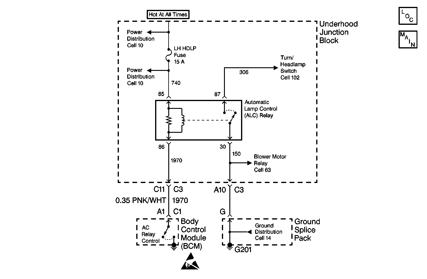
Circuit Description
This is a trouble code (both current and history) that indicates that the automatic light control (ALC) headlamp relay control output is shorted to ground or open.
Conditions for Setting the DTC
Meet all of the following conditions:
| • | The ambient light sensor indicates bright conditions. |
| • | The ALC option is enabled and ignition 1 is active. |
| • | The ignition switch is not in engine crank. |
| - | Ignition 1 is active |
| - | Ignition 3 is inactive |
| - | The engine is not running |
| • | The ALC headlamp output is not active. |
| • | The ALC headlamp feedback is present for 5 seconds. |
Action Taken When the DTC Sets
| • | Stores the DTC B2577 in the body control module (BCM) memory. |
| • | The SERVICE VEHICLE SOON indicator will illuminate. |
Conditions for Clearing the DTC
| • | The BCM reads the proper headlamp voltage. |
| • | Conditions for the fault are no longer present. |
| • | All the BCM history codes will be cleared after 100 ignition cycles (from OFF to RUN) with no current codes active during the 100 ignition cycles. |
| • | Use the Scan Tool . |
Diagnostic Aids
| • | When the diagnostics direct you to take electrical measurements at the junction blocks, refer to Power Distribution Schematics in Wiring Systems for terminal assignments of the junction blocks. |
| • | If the DTC is a history DTC, the problem may be intermittent. Try performing the above tests while wiggling the wiring and connectors. This can often cause the malfunction to appear. |
Test Description
The numbers below refer to the numbers on the diagnostic table.
-
This step verifies proper operation of the of the ALC headlamp relay.
-
This step determines if the underhood junction block has a short to ground in CKT 1970.
-
This step determines in a short to ground exists in CKT 1970 between the underhood junction block and the body control module (BCM).
-
This step determines if an open exists in CKT 1970 between the underhood junction block and the BCM.
Step | Action | Value(s) | Yes | No |
|---|---|---|---|---|
1 | Was the BCM diagnostic system check performed? | -- | Go to Step 2 | Go to the Body Control Module System Check |
Does the automatic lighting control work correctly? | -- | Go to Step 10 | Go to Step 3 | |
Is the measured voltage at the specified value? | B+ | Go to Step 5 | Go to Step 4 | |
4 | Replace the underhood junction block. Refer to Relay/Fuse Center Replacement in Wiring Systems. Is the repair complete? | -- | Go to Step 10 | -- |
Is the measured resistance equal to the specified value? | ∞ | Go to Step 7 | Go to Step 6 | |
6 | Repair the short to ground in CKT 1970 between the BCM connector C1 terminal A1 and the underhood junction block connector C3 terminal C11. Refer to Wiring Repairs in Wiring Systems. Is the repair complete? | -- | Go to Step 10 | -- |
Use the J 39200 DMM in order to measure the resistance in CKT 1970 between the BCM harness connector C1 terminal A1 and the underhood junction block harness connector C3 terminal C11. Is the measured resistance within the specified range? | 0-2 ohms | Go to Step 9 | Go to Step 8 | |
8 | Repair an open in CKT 1970 between the BCM connector C1 terminal A1 and the underhood junction block connector C3 terminal C11. Refer to Wiring Repairs in Wiring Systems. Is the repair complete? | -- | Go to Step 10 | -- |
9 | Replace the BCM. Refer to the following procedures: Is the repair complete? | -- | Go to Step 10 | -- |
10 | Clear the DTCs from the memory. Are the DTCs cleared from the memory? | -- | Go to the Body Control Module System Check | -- |
