Engine Mount Replacement Right Engine Mount
Removal Procedure

- Use a J 28467-A
with a J 28467-89
in order to support the engine.
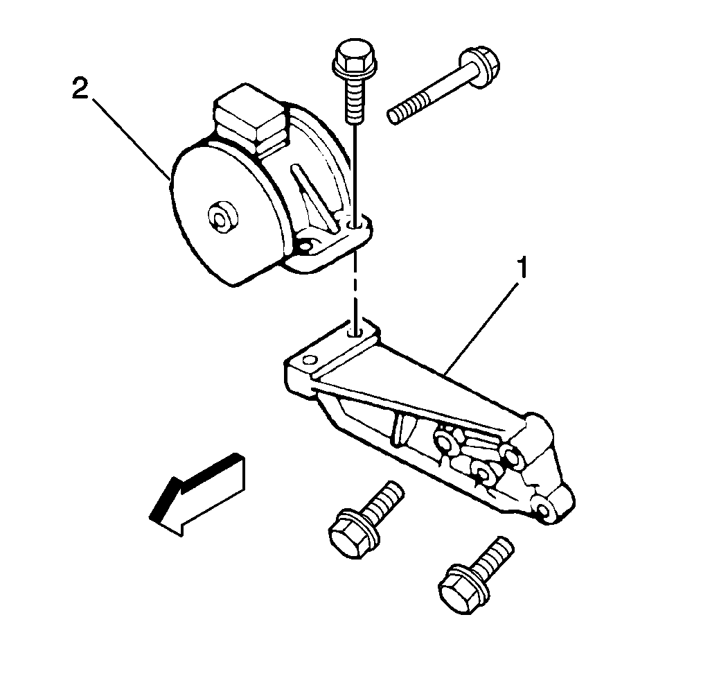
- Remove the two right engine mount-to-mounting bracket bolts.
- Remove the right engine mount through-bolt and the mount (2) from
the mounting bracket (1).
- Remove the two mounting bracket bolts and the right mounting bracket
(1) from the vehicle.
Installation Procedure
Tools Required

- Install the right mounting
bracket (1) to the vehicle.
- Secure the mounting bracket (1) with the two mounting bracket
bolts. Do not tighten fully.
- Install the right engine mount (2) and through-bolt to the mounting
bracket (1).
- Secure the right engine mount with the two right engine mount-to-mounting
bracket bolts.
Notice: Use the correct fastener in the correct location. Replacement fasteners
must be the correct part number for that application. Fasteners requiring
replacement or fasteners requiring the use of thread locking compound or sealant
are identified in the service procedure. Do not use paints, lubricants, or
corrosion inhibitors on fasteners or fastener joint surfaces unless specified.
These coatings affect fastener torque and joint clamping force and may damage
the fastener. Use the correct tightening sequence and specifications when
installing fasteners in order to avoid damage to parts and systems.
- Tighten the fasteners.
Tighten
| • | Tighten the right engine mount through-bolt to 55 N·m
(41 lb ft). |
| • | Tighten the right engine mount-to-mounting bracket bolts to 55 N·m
(41 lb ft). |
| • | Tighten the mounting bracket bolts to 55 N·m (41 lb ft). |
- Remove the J 28467-A
and the J 28467-89
.
Engine Mount Replacement Rear Engine Mount - Manual
Removal Procedure

- Use a J 28467-A
with a J 28467-89
in order to support the engine.
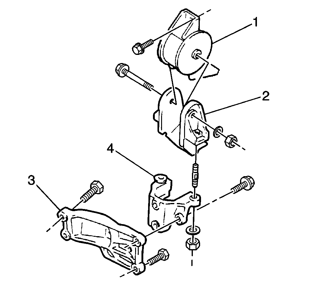
- Remove the nut and rear engine mount through bolts from the rear
engine mount (1).
- Remove the two rear engine mount-to-bulkhead bolts.
- Remove the rear engine mount (1) from the upper mounting bracket
(2).
- Remove the two retaining nuts and the upper mounting bracket (2)
from the lower rear mounting bracket (4).
- Remove the three retaining bolts and the upper rear mounting bracket
from the vehicle.
Installation Procedure
Tools Required

- Install the lower rear
mounting bracket (4) to the vehicle.
- Secure the lower bracket with the three retaining bolts. Do not
tighten firmly.
- Install the upper rear mounting bracket (2) to the lower rear
mounting bracket (4).
- Secure the upper bracket with the two retaining nuts. Do not tighten
fully.
- Install the rear engine mount (1) to the upper rear mounting bracket
(2).
- Secure the engine mount with the two rear engine mount-to-bulkhead
bolts. Do not tighten fully.
- Install the rear engine mount through bolt to the rear engine
mount.
Notice: Use the correct fastener in the correct location. Replacement fasteners
must be the correct part number for that application. Fasteners requiring
replacement or fasteners requiring the use of thread locking compound or sealant
are identified in the service procedure. Do not use paints, lubricants, or
corrosion inhibitors on fasteners or fastener joint surfaces unless specified.
These coatings affect fastener torque and joint clamping force and may damage
the fastener. Use the correct tightening sequence and specifications when
installing fasteners in order to avoid damage to parts and systems.
- Tighten the fasteners.
Tighten
| • | Tighten the rear engine mount through bolt and nut to 55 N·m
(41 lb ft). |
| • | Tighten the rear engine mount-to-bulkhead bolt to 55 N·m
(41 lb ft). |
| • | Tighten the upper rear mounting bracket retaining nuts to 55 N·m
(41 lb ft). |
| • | Tighten the lower rear mounting bracket retaining bolts and nuts
to 55 N·m (41 lb ft). |
- Remove the J 28467-A
and the J 28467-89
.
Engine Mount Replacement Rear Engine Mount - Automatic
Removal Procedure

- Use a J 28467-A
with a J 28467-89
in order to support the engine.
- Drain the engine coolant. Refer to
Cooling System Draining and Filling
in Engine Cooling.
- Raise and support the vehicle. Refer to
Lifting and Jacking the Vehicle
in General Information.
Caution: In order to avoid being burned, do not service the exhaust system while
it is still hot. Service the system when it is cool.
- Remove the two bolts and the front pipe/catalytic converter assembly
from the exhaust manifold.
- Remove the two nuts and the front pipe/catalytic converter assembly
from the resonator/center pipe.
- Remove the hanger that supports the catalytic converter.
- Remove the front pipe/catalytic converter assembly from the vehicle.
- Remove the following from the engine:
| • | The coolant return pipe |
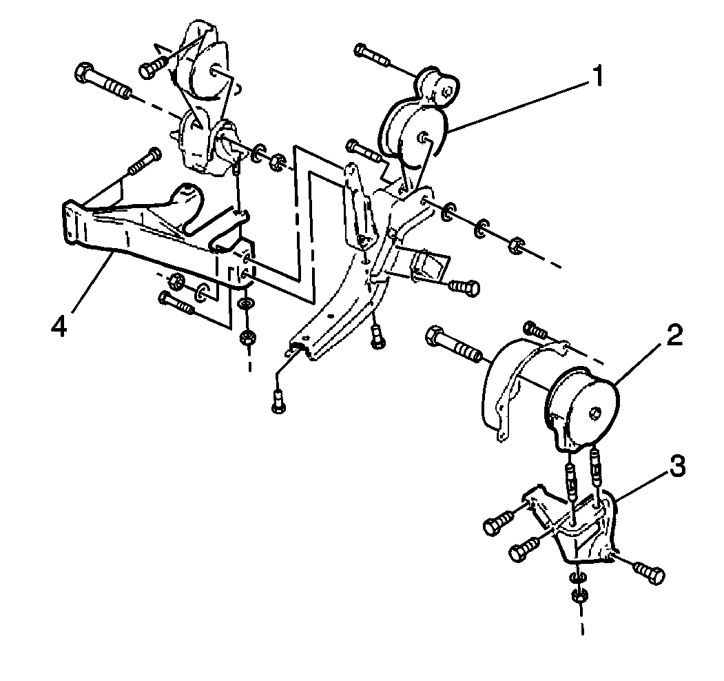
- Remove the two nuts and the rear engine mount connecting bracket
from the rear engine mount frame bracket (4).
- Remove the following components from the engine:
| • | The rear engine mount-to-engine bracket |
- Remove the four bolts that hold the rear engine mount frame bracket
to the frame.
- Remove the rear engine mount frame bracket from the frame.
- Remove the one nut and the connecting bracket from the rear engine
mount.
- Remove the one nut and the rear engine mount-to-engine bracket
from the rear engine mount.
Installation Procedure

- Use a J 28467-A
with a J 28467-89
in order to support the engine.
- Install the rear engine mount frame bracket (4) to the frame.
- Secure the frame bracket with four bolts. Do not tighten fully.
- Install the rear engine mount-to engine bracket to engine.
- Secure the mount with two bolts and one nut. Do not install the
lower center bolt at this time. Do not tighten fully.
- Install the rear engine mount to the bracket. Secure with one
nut.
- Install the connecting bracket to the rear engine mount. Secure
with one nut. Do not tighten fully.
- Install the rear engine mount connecting bracket to the rear engine
mount frame bracket. Secure with two nuts.
Notice: Use the correct fastener in the correct location. Replacement fasteners
must be the correct part number for that application. Fasteners requiring
replacement or fasteners requiring the use of thread locking compound or sealant
are identified in the service procedure. Do not use paints, lubricants, or
corrosion inhibitors on fasteners or fastener joint surfaces unless specified.
These coatings affect fastener torque and joint clamping force and may damage
the fastener. Use the correct tightening sequence and specifications when
installing fasteners in order to avoid damage to parts and systems.
- Tighten the fasteners.
Tighten
| • | Tighten the rear engine mount frame bracket-to-frame bolts to
55 N·m (41 lb ft). |
| • | Tighten the rear mount-to-engine bracket to the engine bolts and
nut to 55 N·m (41 lb ft). |
| • | Tighten the rear engine mount connecting bracket-to-rear engine
mount frame bracket nuts to 55 N·m (41 lb ft). |
| • | Tighten the connecting bracket-to-rear mount nut to 55 N·m
(41 lb ft). |
| • | Tighten the rear mount-to-engine bracket nut to 55 N·m
(41 lb ft). |
- Install the one remaining rear engine mount frame bracket-to-frame
bolt.
Tighten
Tighten the rear engine mount frame bracket-to-frame bolt to 55 N·m
(41 lb ft).
- Install the following components:
| • | The coolant return pipe |
Tighten
Tighten the coolant return pipe mounting bolts to 20 N·m
(15 lb ft).
- Install the front pipe/catalytic converter assembly to the vehicle.
- Support the catalytic converter with the hanger.
- Connect the front pipe/catalytic converter assembly to the exhaust
manifold.
- Secure the converter assembly with two bolts. Do not tighten fully.
- Connect the front pipe/converter assembly to the resonator/center
pipe.
- Secure the converter assembly to the resonator/center pipe with
the two nuts.
Tighten
| • | The front exhaust pipe/catalytic converter assembly-to-exhaust
manifold bolts to 55 N·m (41 lb ft). |
| • | The front exhaust pipe/catalytic converter assembly-to-resonator/center
pipe nuts to 35 N·m (26 lb ft). |
- Lower the vehicle.
- Refill the engine coolant. Refer to
Cooling System Draining and Filling
in Engine Cooling.
- Remove the J 28467-A
and the J 28467-89
.
Engine Mount Replacement Left Transaxle Mount
Refer to
Transmission Mount Replacement
in Manual Transmission/Transaxle for the removal and installation
procedures of the left engine (transaxle) mount.
Engine Mount Replacement Torque Rod Automatic Trans
Removal Procedure

- Use a J 28467-A
with a J 28467-89
in order to support the engine.
- Raise and support the vehicle. Refer to
Lifting and Jacking the Vehicle
in General Information.
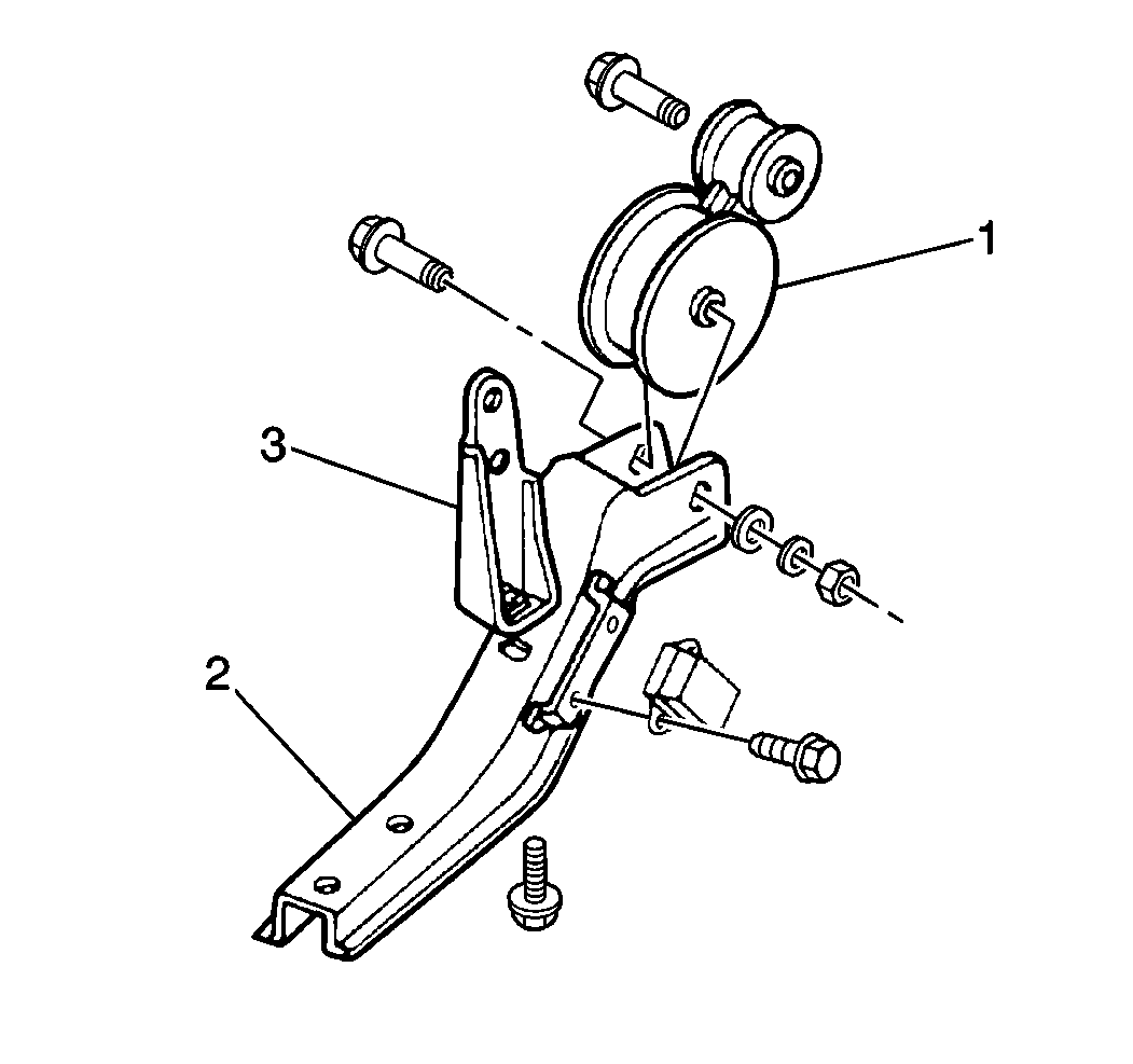
- Remove the retaining nut and the torque rod-to-torque rod bracket
through bolt and washers.
- Remove the four bolts and the torque rod bracket (2) from the
transaxle.
- Remove one torque rod-to-torque rod brace bolt.
- Remove the torque rod-to-frame through bolt.
- Remove the torque rod (1) from the engine.
Installation Procedure

- Install the torque rod
(1) to the engine. Secure the torque rod (1) with the torque rod-to-frame
through bolts. Do not tighten fully.
- Install the torque rod bracket (2) to the transaxle. Secure the
torque rod bracket to the transaxle with the four bolts. Do not tighten fully.
- Install the torque rod-to-torque rod brace bolt. Do not tighten
fully.
- Install the torque rod-to-torque rod bracket through bolt and
washer. Secure with the retaining nut.
Notice: Use the correct fastener in the correct location. Replacement fasteners
must be the correct part number for that application. Fasteners requiring
replacement or fasteners requiring the use of thread locking compound or sealant
are identified in the service procedure. Do not use paints, lubricants, or
corrosion inhibitors on fasteners or fastener joint surfaces unless specified.
These coatings affect fastener torque and joint clamping force and may damage
the fastener. Use the correct tightening sequence and specifications when
installing fasteners in order to avoid damage to parts and systems.
- Tighten the fasteners.
Tighten
| • | Tighten the torque rod-to-torque rod bracket through bolt and
nut to 55 N·m (41 lb ft). |
| • | Tighten the torque rod bracket bolts to 55 N·m (41 lb ft). |
| • | Tighten the torque rod-to-frame through bolt to 55 N·m
(41 lb ft). |
- Lower the vehicle.
- Remove the J 28467-A
and the J 28467-89
.


