Removal Procedure
- Remove the negative (-) battery cable.
- Disconnect the distributor electrical connector.
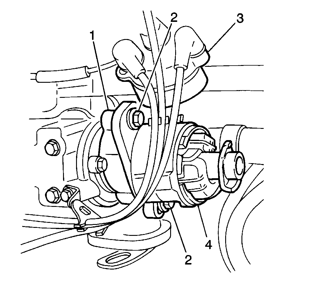
- Remove two screws and the distributor cap from the distributor.
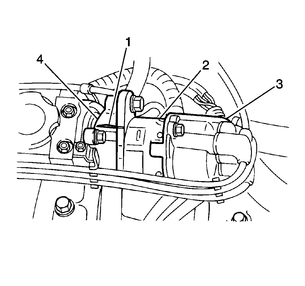
- Mark the distributor housing (1) position on the cylinder head (4).
- Remove two distributor flange bolts (2) and the distributor housing (4) from the cylinder head.
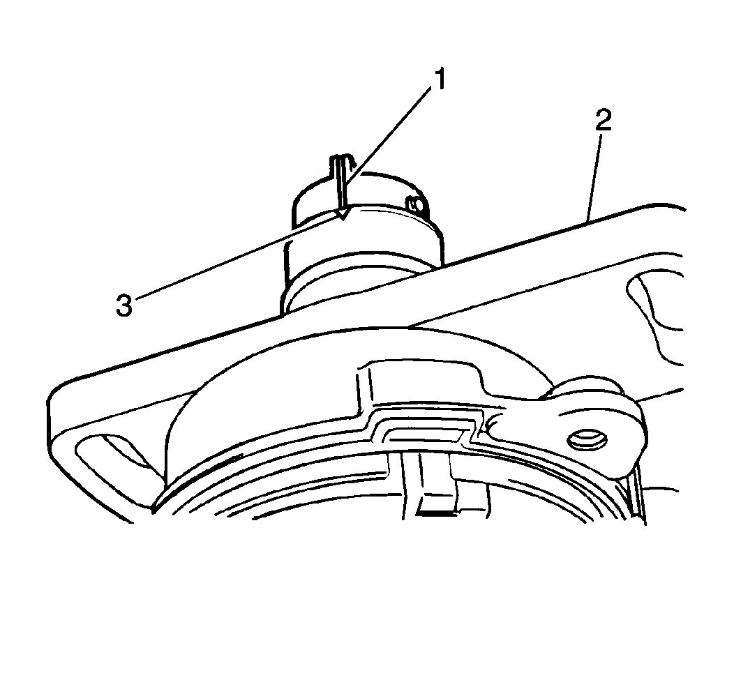
- Mark the distributor coupling position (1) on the distributor housing (2).
- Inspect the distributor cap and the rotor for cracks, terminal corrosion and wear. Replace as necessary.
Caution: Unless directed otherwise, the ignition and start switch must be in the OFF or LOCK position, and all electrical loads must be OFF before servicing any electrical component. Disconnect the negative battery cable to prevent an electrical spark should a tool or equipment come in contact with an exposed electrical terminal. Failure to follow these precautions may result in personal injury and/or damage to the vehicle or its components.


If Distributor Position Was Lost
Tool Required
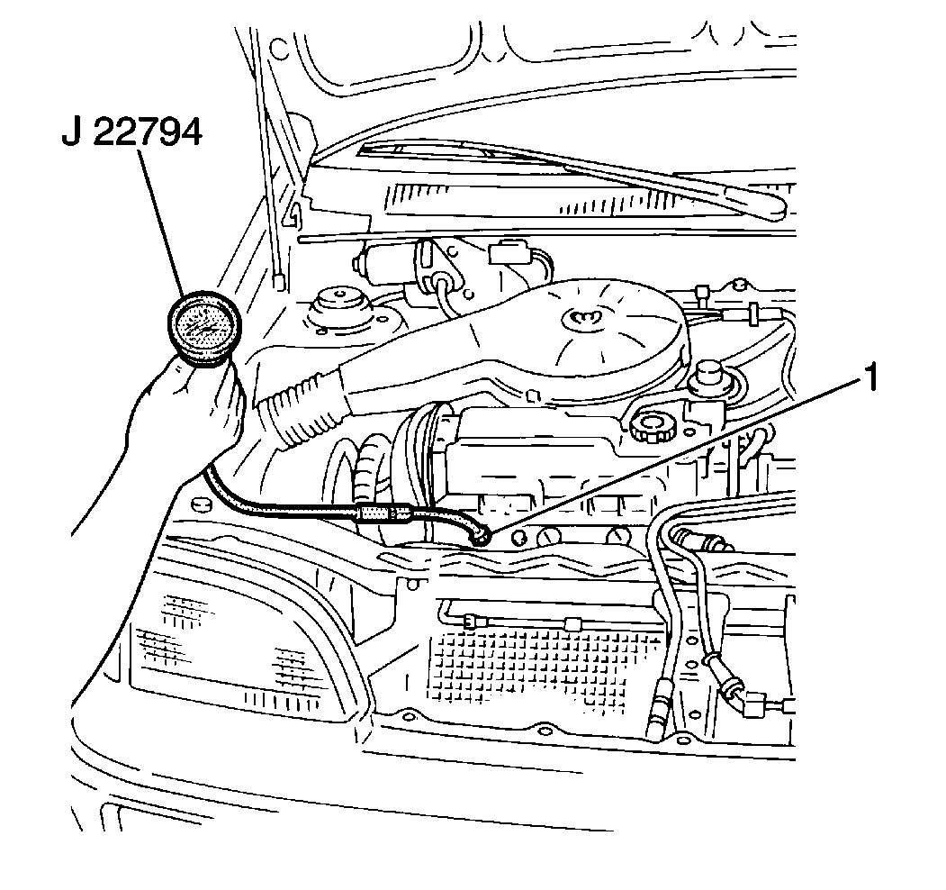
J 22794 Spark Plug Port Adaptor
If the engine was accidently cranked after the distributor was removed, the following procedure can be used to properly position the distributor.
- Crank the engine until the number 1 cylinder is at top dead center (TDC) on the compression stroke. This can be accomplished by the following:
- Align the timing mark on the crankshaft pulley to the zero (0) position on the timing indicator.
- Position the rotor to the number 1 cylinder position.
- Install the distributor.
- Remove the J 22794 spark plug port adaptor and the compression gauge.
- Install the number 1 spark plug.
- Install the FI fuse into the fuse and relay box.
- Set the ignition timing. Refer to Ignition Timing Adjustment .
| 1.1. | Remove the FI fuse from the fuse and relay box. |
| 1.2. | Remove the number 1 spark plug. Refer to Spark Plug Replacement . |

| 1.3. | Install a J 22794 spark plug port adaptor and a compression gauge into the spark plug cavity. |
| 1.4. | Crank the engine and observe the compression gauge. The TDC of the cylinder's compression stroke occurs when the compression reading is the highest. |
Tighten
Tighten the spark plug to 28 N·m (21 lb ft).
Installation Procedure
- Match the distributor coupling-to-distributor housing alignment marks (1,3).
- Install the distributor housing (2) to the cylinder head (4). Match the marks made on the cylinder head and the distributor housing during removal.
- Install two distributor flange bolts (2). Do no tighten fully.
- Install the new distributor cap seal to the distributor cap.
- Install the distributor cap to the distributor. Secure the cap with two screws.
- Connect the distributor electrical connector.
- Connect the negative (-) battery cable.
- Set the ignition timing on the 1.0L only. Refer to Ignition Timing Adjustment in Engine Controls.


Notice: Use the correct fastener in the correct location. Replacement fasteners must be the correct part number for that application. Fasteners requiring replacement or fasteners requiring the use of thread locking compound or sealant are identified in the service procedure. Do not use paints, lubricants, or corrosion inhibitors on fasteners or fastener joint surfaces unless specified. These coatings affect fastener torque and joint clamping force and may damage the fastener. Use the correct tightening sequence and specifications when installing fasteners in order to avoid damage to parts and systems.
Tighten
Tighten the negative (-) battery cable-to-negative (-)
battery terminal retainer to 15 N·m (11 lb ft).
