Removal Procedure
Tools Required
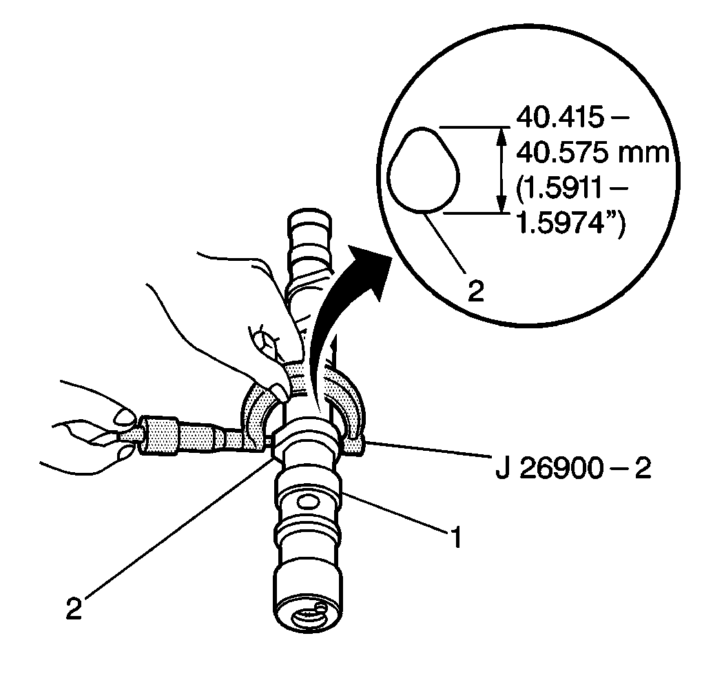
J 26900-2 Outside Micrometer
- Disconnect the negative battery cable.
- Remove the Valve Rocker Arm Cover. Refer to Valve Rocker Arm Cover Replacement in Engine Mechanical.
- Remove the distributor. Refer to Distributor Replacement in Engine Electrical.
- Remove the distributor housing.
- Raise and support the vehicle. Refer to Lifting and Jacking the Vehicle in General Information.
- Remove the timing belt. Refer to Timing Belt Replacement in Engine Mechanical.
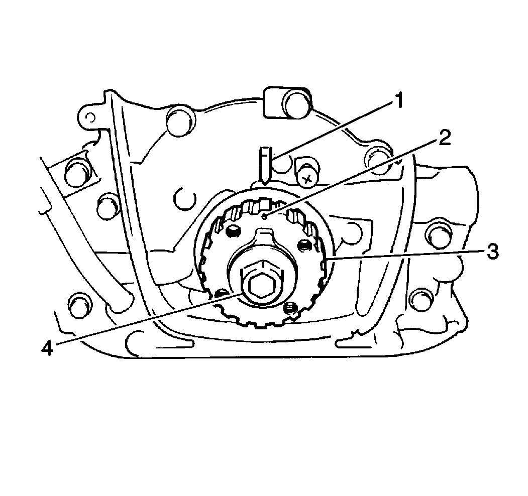
- Remove the camshaft timing gear.
- Ensure that the crankshaft is in the correct position before proceeding.
- Remove the six bolts and the three camshaft housings from the cylinder head.
- Remove the camshaft from the cylinder head.
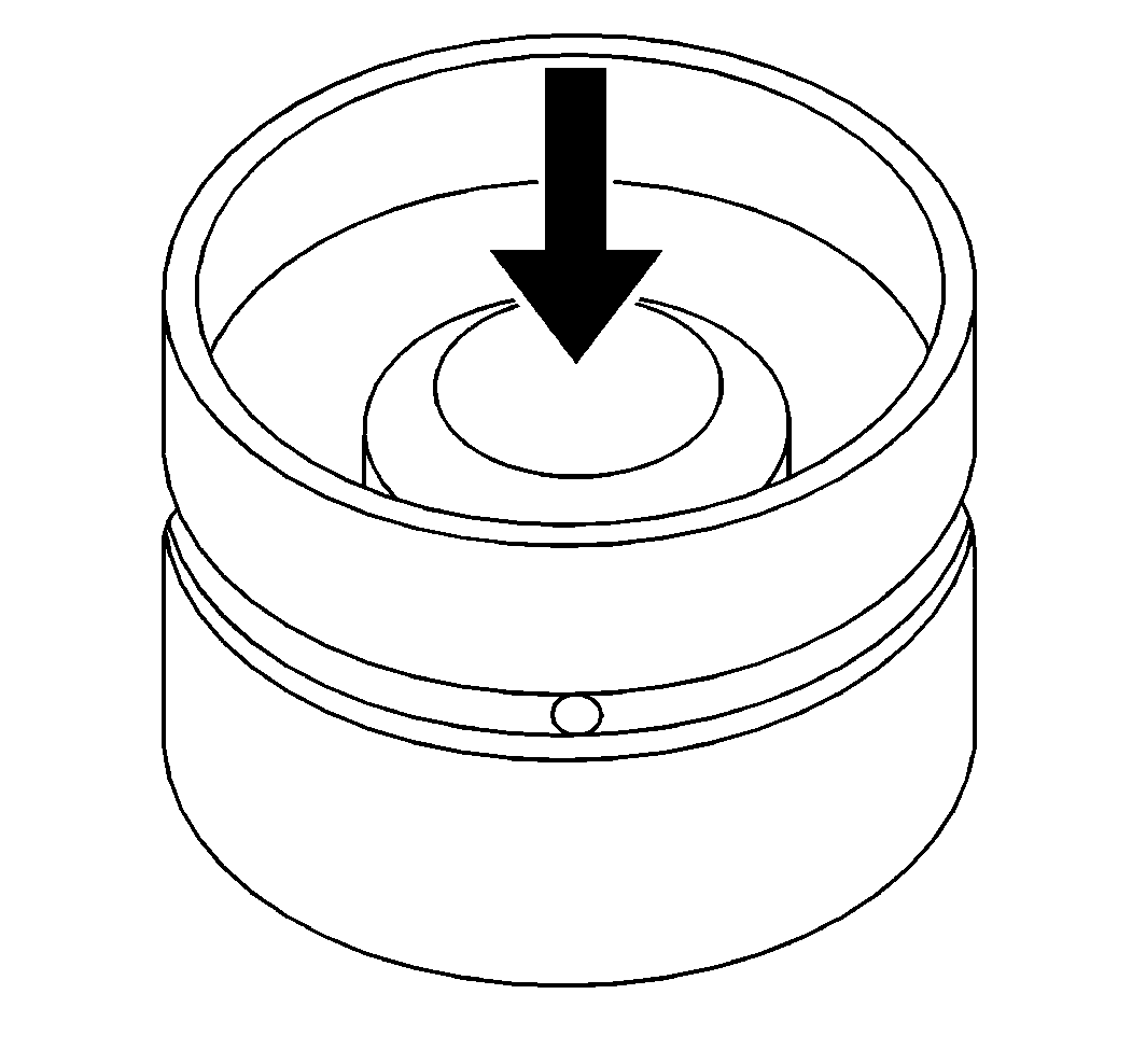
- Remove the six Hydraulic Valve Lash (HVL) Adjusters from the cylinder head.
Caution: Unless directed otherwise, the ignition and start switch must be in the OFF or LOCK position, and all electrical loads must be OFF before servicing any electrical component. Disconnect the negative battery cable to prevent an electrical spark should a tool or equipment come in contact with an exposed electrical terminal. Failure to follow these precautions may result in personal injury and/or damage to the vehicle or its components.

Important: Use a suitable holding tool to keep the camshaft gear from turning while removing the retaining bolt.
Important:
• Never disassemble the Hydraulic Valve Lash (HVL) adjuster. • Do not apply force to the body of the adjuster or the oil in the
high pressure chamber. • Submerge the removed adjusters in clean engine oil until reinstallation.
If the adjusters are left in the air, place with the adjuster bodies facing
down. Do not place on the side or with the adjuster bodies facing up.
Inspect
| • |
|
| - | Standard camshaft lobe height is 40.415 to 40.575 mm (1.5911 to 1.5974 in). |
| - | Minimum camshaft lobe height is 40.315 mm (1.5872 in) |
| • |
Installation Procedure
- Pour engine oil through the camshaft journal holes (2).
- Inspect that the engine oil comes out from the oil holes in the HVL adjuster bores.
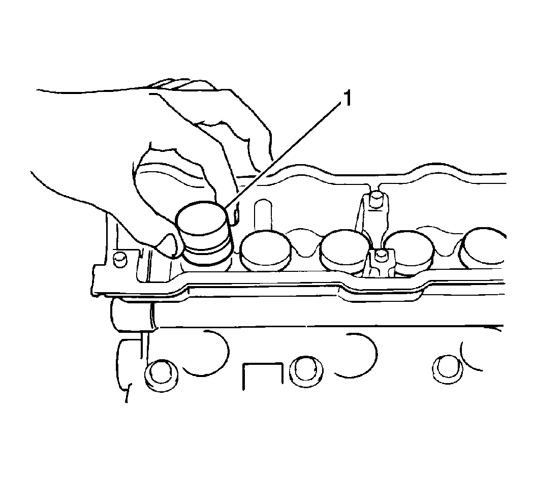
- Apply engine oil around the HVL adjuster.
- Install the HVL adjuster (1) to the cylinder head.
- Apply engine oil to the camshaft journal and around all of the cams.
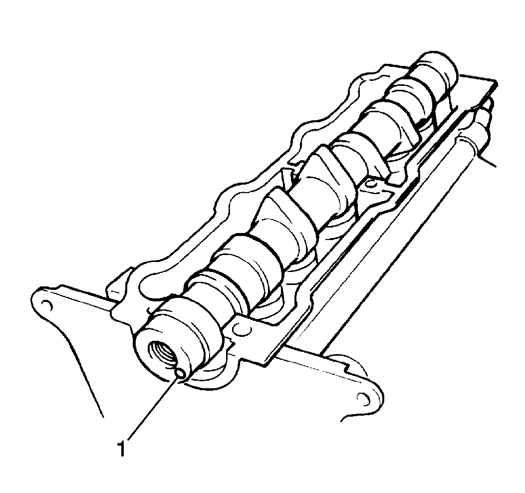
- Install the camshaft into the cylinder head so that the camshaft timing gear pin hole (1) in the camshaft is at the lower position.
- Apply engine oil to the sliding surface of each housing against the camshaft journal.
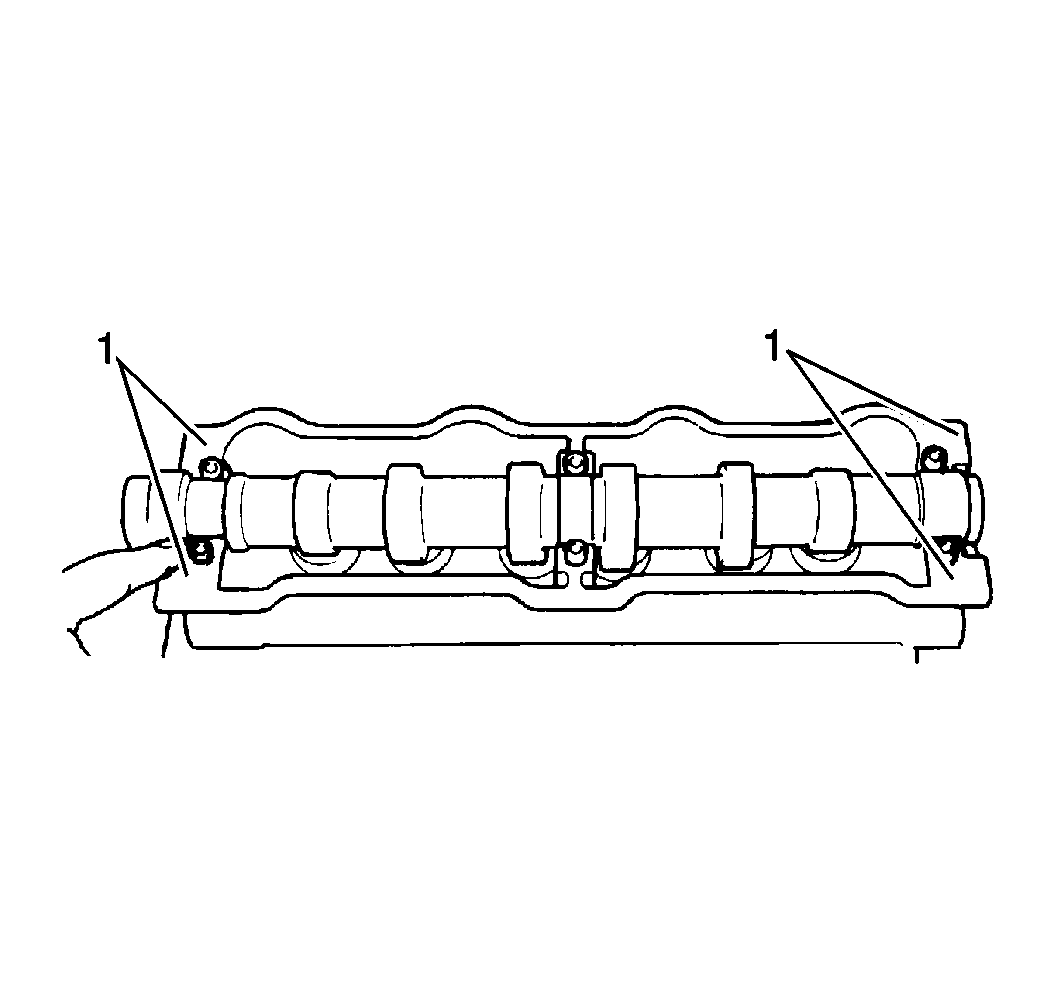
- Apply GM P/N 12346240 or equivalent, to the mating surface of the No. 1 and No. 3 housings (1) which will mate with the cylinder head.
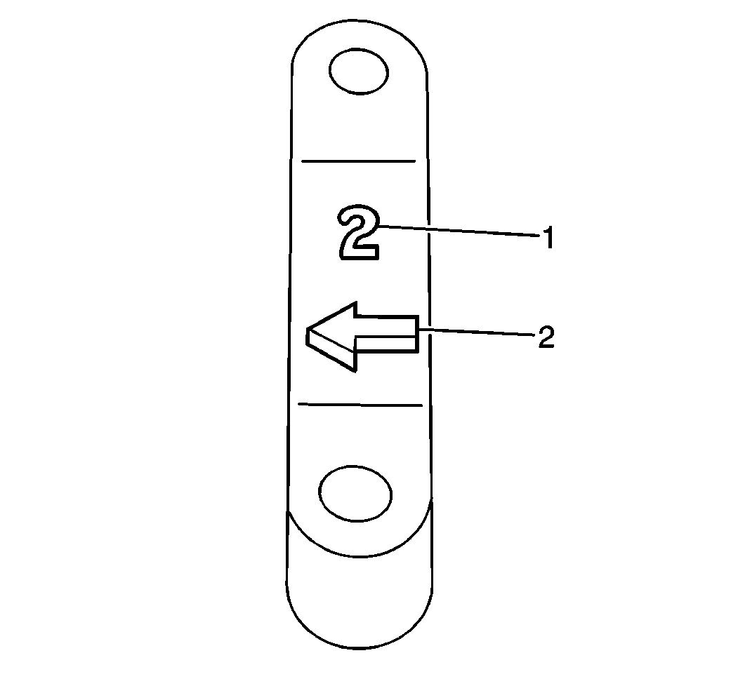
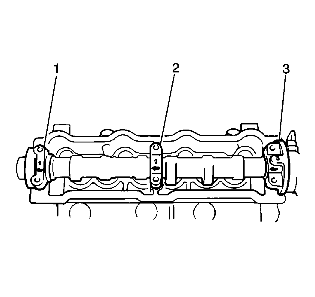
- Install the camshaft housing No.1 (1) to the camshaft and the cylinder head with the arrow on the camshaft housing (2) facing the timing belt side.
- Install the two remaining camshaft housings (2, 3) to the journals of the camshaft.
- Secure the camshaft housings with the housing bolts.
- Apply engine oil to the camshaft oil seal lip.
- Press-fit the camshaft oil seal until the oil seal surface becomes flush with the housing surface.
- Install the dowel pin to the camshaft timing gear pin hole (1).
- Install the camshaft timing gear.
- Secure the camshaft timing gear with the camshaft timing gear bolt.
- Apply a small amount of GM P/N 12346240 or equivalent, to the corners of the cylinder head gasket.
- Install the new cylinder head cover gasket to the cylinder head cover.
- Install the cylinder head cover to the cylinder head and secure the cylinder head cover with new seal washers and cover nuts.
- Install the distributor case and distributor to the cylinder head. Refer to Distributor Replacement in Engine Electrical.
- Install the timing belt. Refer to Timing Belt Replacement in Engine Mechanical.
- Connect the negative battery cable.
- When the engine is started, if air is trapped in the HVL adjuster, the valve may make a tapping sound when the engine is operated after the HVL adjuster is installed. In such a case, run the engine slightly above the idle speed as necessary until the air is purged and the tapping sound ceases. Should the tapping noise not cease within a half an hour, one or more HVL adjusters could be faulty. If the faulty adjuster can not be located by ear, perform the following steps:
- Listen for tapping noises from the engine.
- If no noises are heard, adjust the ignition timing.
- Turn the ignition switch to the OFF position.
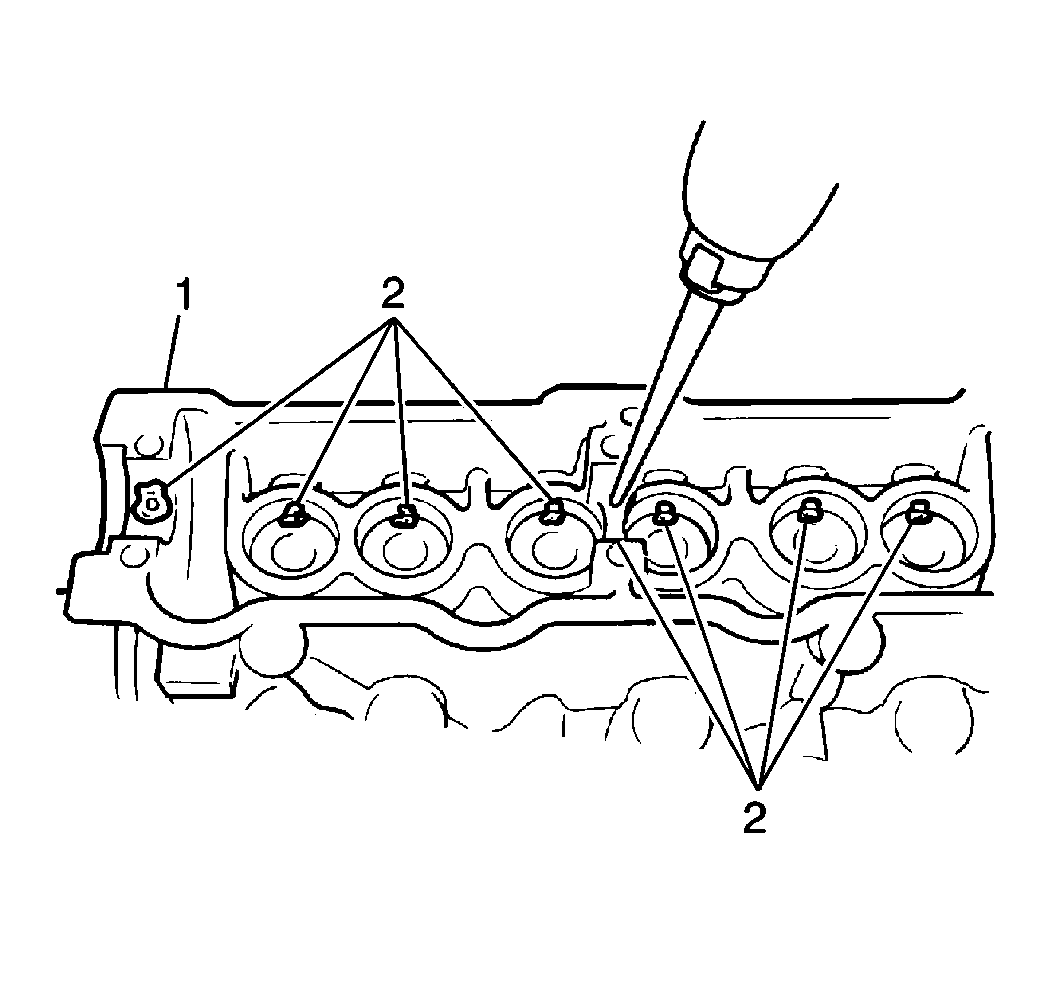
Important: The camshaft housing No. 1 retains the camshaft in the proper position as to the thrust direction. Install the housing No. 1 to the journal No. 1 first. Do not tighten fully.
Important: Apply engine oil to the housing bolts before securing the camshaft housings to the camshaft journals.
Notice: Use the correct fastener in the correct location. Replacement fasteners must be the correct part number for that application. Fasteners requiring replacement or fasteners requiring the use of thread locking compound or sealant are identified in the service procedure. Do not use paints, lubricants, or corrosion inhibitors on fasteners or fastener joint surfaces unless specified. These coatings affect fastener torque and joint clamping force and may damage the fastener. Use the correct tightening sequence and specifications when installing fasteners in order to avoid damage to parts and systems.
Tighten
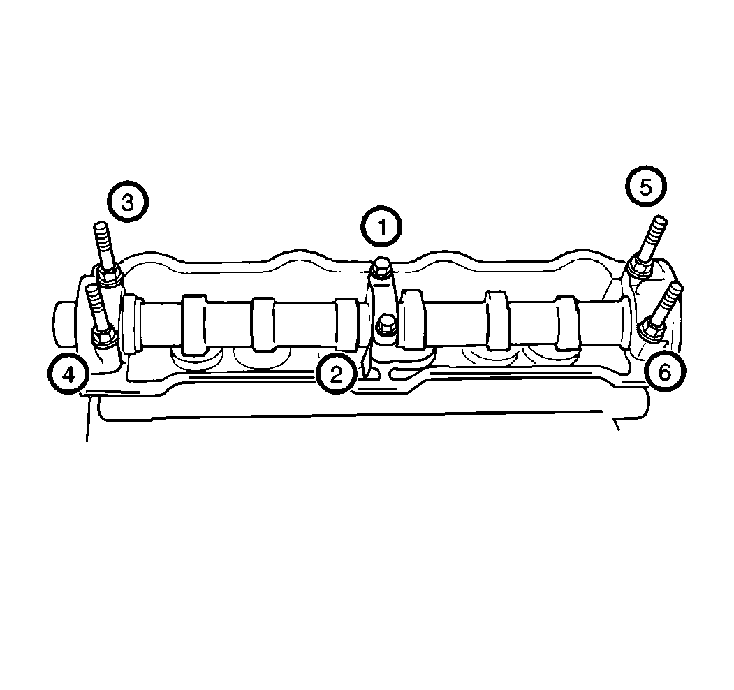
Tighten the bolts a little at a time and evenly among the bolts. Repeat
the tightening process three or four times until they are tightened to 11 N·m
(97 lb in).

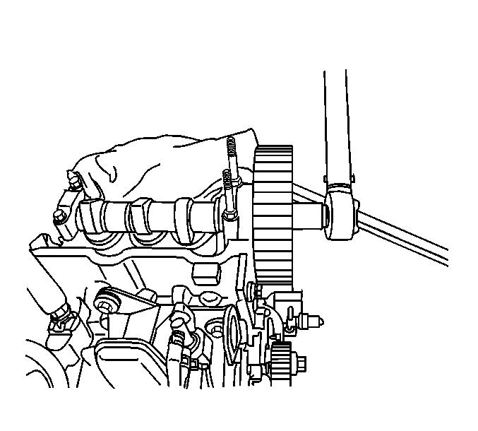
Important: Use a suitable holding tool to keep the camshaft gear from turning while installing the retaining bolt.
Tighten
Tighten the camshaft timing gear bolt to 60 N·m (44 lb ft).
Notice: Ensure the sealant applied to the component does not block or restrict any passages. A blocked or restricted passage can cause improper flow. Improper flow can lead to component leakage or cause extensive engine damage.
Tighten
Tighten the cylinder head cover nuts to 5 N·m (44 lb in).
Notice: Do not turn the camshaft or start the engine (i,e., the valves should not be operated) for about a half an hour after reinstalling the HVL adjusters and the camshaft. Since it takes time for the HVL adjusters to settle in place, operating the engine within a half an hour after their installation may cause interference to occur between the valves and the piston.
| • | Turn the ignition switch to the OFF position. |
| • | Remove the cylinder head cover. |
| • | Inspect that the cam lobe is not on the HVL adjuster to be checked. |
| • | Push the HVL adjuster downward by hand (with less than 15 kg or 33 lbs force). |
| • | Inspect if there is clearance between the cam and the adjuster. If there is clearance between the cam and the adjuster, the adjuster is defective and must be replaced. |
