For 1990-2009 cars only
Disassembly Procedure
- Remove the manual steering gear from the vehicle. Refer to Manual Steering Gear Replacement .
- Loosen the 2 outer tie rod end locknuts.
- Remove the 2 outer tie rod ends from the inner tie rods.
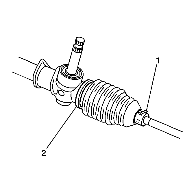
- Remove the retaining clamps (1,2) and the boots from the inner tie rods.
- Unstake the ball nut.
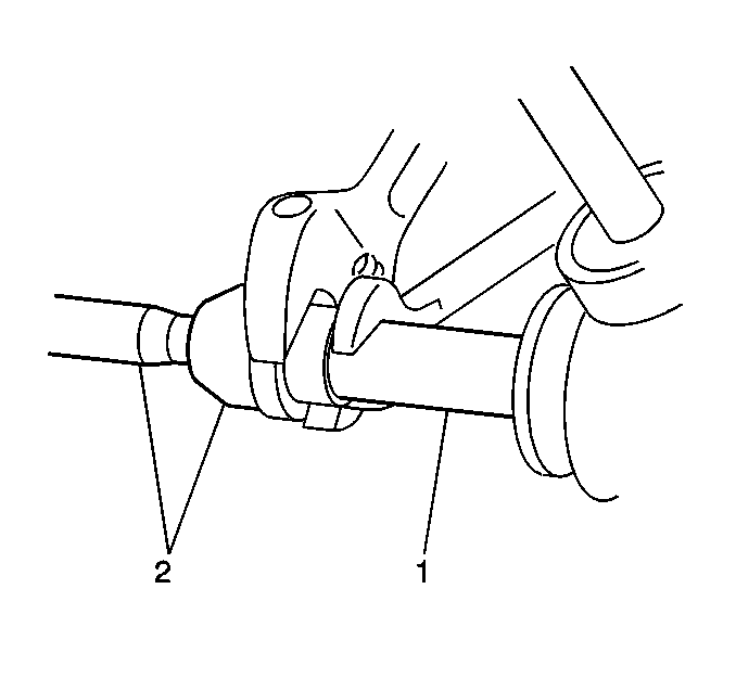
- Remove the inner tie rods (2) from the rack (1).
- Clean the dirt and the grease from all of the steering gear parts using an appropriate solvent.
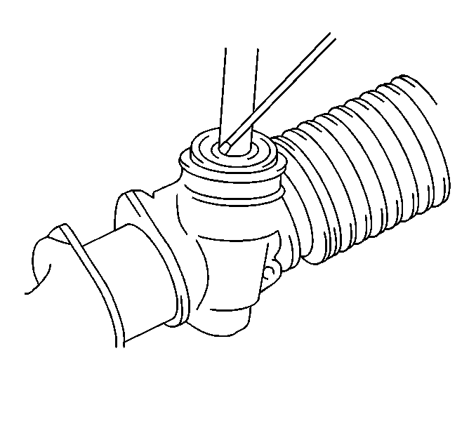
- Remove the pinion seal.
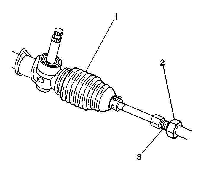
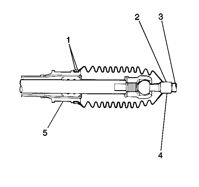
Important: Mark the position of the outer tie rod end locknut (2) on the inner tie rod thread (3).
Inspection Procedure
Tools Required
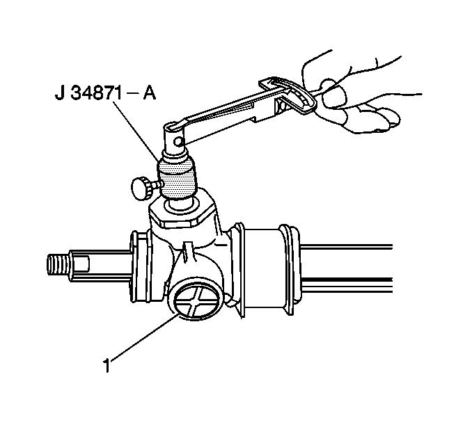
J 34871-A Pinion Socket
- Inspect the pinion oil seal for wear or for damage.
- Inspect the steering rack boots for the following conditions:
- Replace the steering rack boots if the boots are faulty.
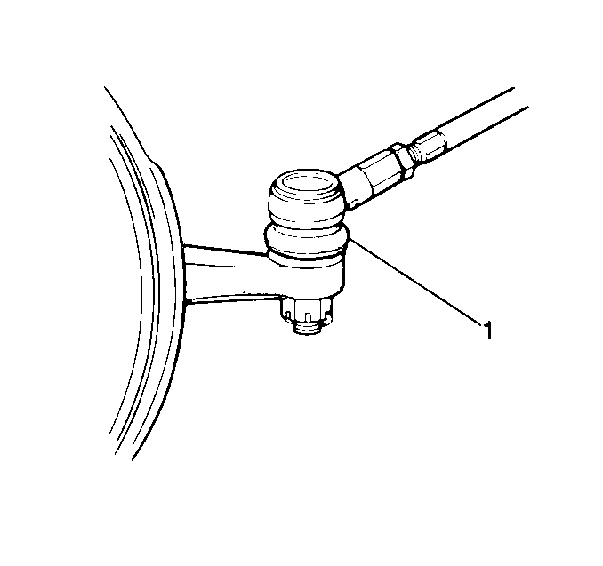
- Inspect the dust seal (1) for the following conditions:
- Replace the seal (1) if the seal is worn.
- Measure the pinion's resistance to rotation using a torque wrench and the J 34871-A .
- If the resistance to rotation is not within specification, replace the steering gear. Refer to Manual Steering Gear Replacement .
Notice: A torn boot allows entry of dirt and moisture into the steering gear
assembly. This can produce the following conditions that result
in the malfunction of the steering system:
• Noise • Rust and/or wear to the rack and pinion
| • | Wear |
| • | Deterioration |
| • | Tears |
| • | Wear |
| • | Deterioration |
| • | Tears |
Specification
Pinion's resistance to rotation should be 1.0-1.58 N·m (9.0-12.96 lb in).
Assembly Procedure
Tools Required
J 22610 Service Boot Clamp Installer
- If replacing the ball stud dust seal (1), coat the inside of the seal with Chassis Grease, GM P/N 12377985.
- Install the seal to the ball stud.
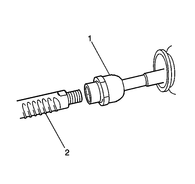
- Install 2 new inner tie rods (1) to the rack (2).
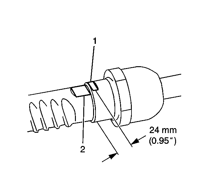
- Tighten the ball nut of each inner tie rod.
- Stake each ball nut until the flat spots (1) are 24 mm (0.95 in) apart.
- Apply manual steering gear lubricant, GM P/N 1052182, or the equivalent, to the inside of the outer end of each boot.
- Position the boots on the grooves of the steering gear housing and the inner tie rods.
- Install the outer boot clamp.
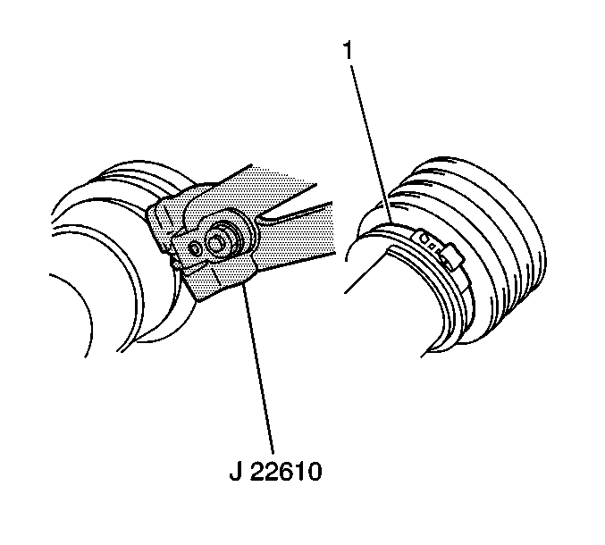
- Install a new inner boot clamp (1), and secure the clamp using the J 22610 .
- Verify that the boots meet the following conditions:
- Position the outer tie rod end locknuts (2) at the mark on the inner tie rod thread (3).
- Install the outer tie rod ends to the inner tie rods.
- Install the manual steering gear to the vehicle. Refer to Manual Steering Gear Replacement .

Tighten
Tighten the ball nuts to 70 N·m (51 lb ft).
| • | The boots are not twisted or folded incorrectly. |
| • | The boot fasteners are secure. |

Important: Copy the marks from the old inner tie rod to the new inner tie rod.
