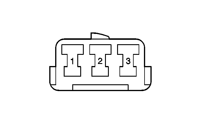
For 1990-2009 cars only
| Table 1: | A/C Compressor Control Module |
| Table 2: | A/C Switch |

| |||||||
|---|---|---|---|---|---|---|---|
Connector Part Information |
| ||||||
Pin | Wire Color | Circuit No. | Function | ||||
1 | BLU/RED | -- | A/C Idle-Up Control | ||||
2-3 | -- | -- | Not Used | ||||
4 | WHT/BLU | -- | Evaporator Temperature Input | ||||
5 | LT GRN/RED | -- | A/C Off Signal | ||||
6 | -- | -- | Not Used | ||||
7 | PNK | -- | A/C 1 Relay (Compressor Clutch) Control | ||||
8 | BLK/WHT | -- | Ignition Power - IG-COIL Fuse | ||||
9 | BLK | -- | G201 | ||||
10 | YEL/GRN | -- | Sensor Ground - Evaporator Thermistor | ||||
11 | BLU/WHT | -- | A/C Request Signal | ||||
12 | ORN/BLK | -- | Dual Pressure Switch Signal | ||||

| ||||||
|---|---|---|---|---|---|---|
Connector Part Information |
| |||||
Pin | Wire Color | Function | ||||
1 | PNK/BLK | Blower Speed Selector Switch | ||||
2 | BLU/WHT | A/C Request | ||||
3 | BLK | Ground | ||||
