Removal Procedure
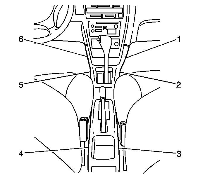
- Remove the 6 screws from the console (1,2,3,4,5,6).
- Remove the center console from the vehicle.
- Remove the rear console from the vehicle.
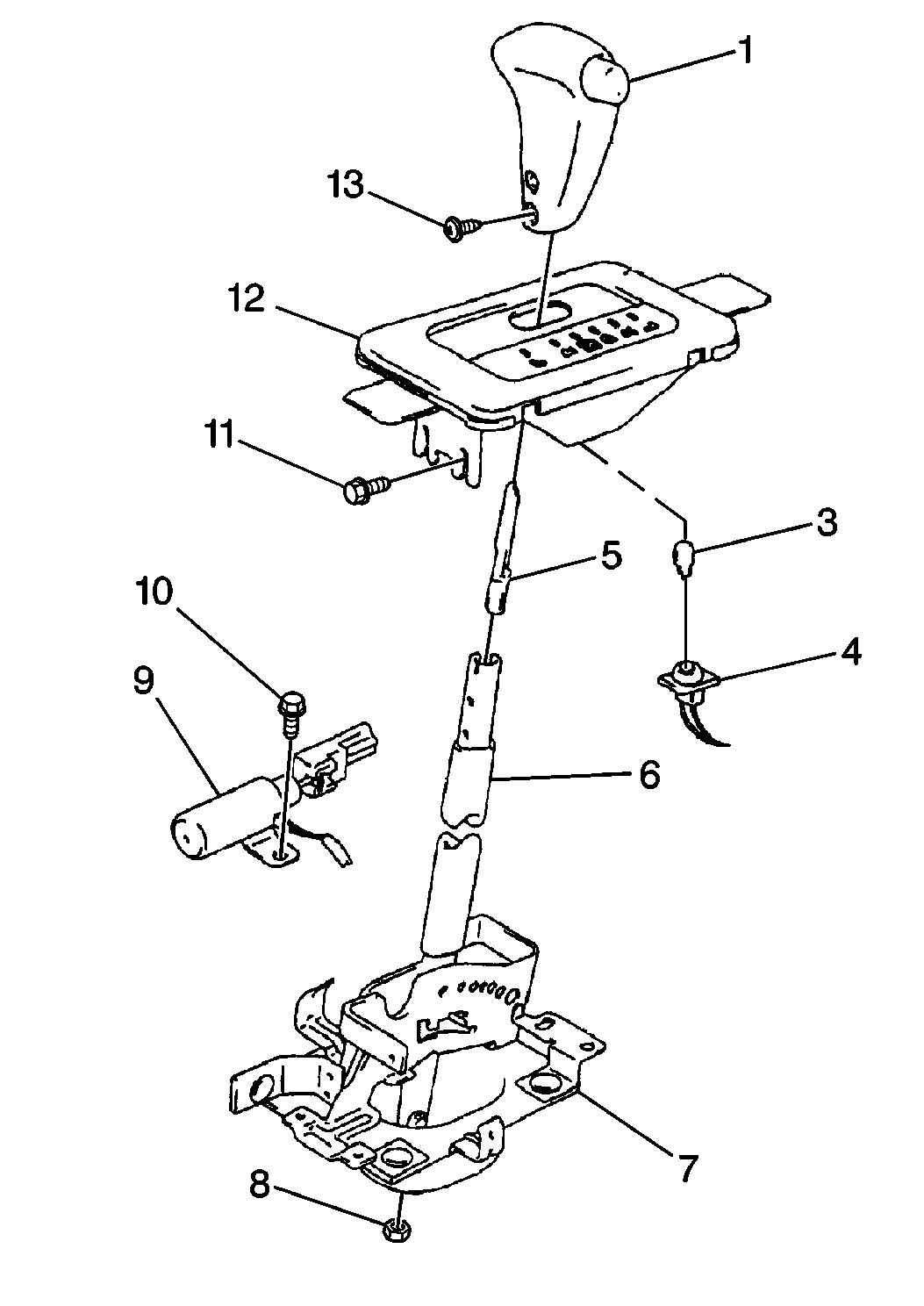
- Remove the two screws and the selector knob (1) from the selector lever (6).
- Remove the 4 screws and the manual selector cover (12) from the selector lever.
- Remove the interlock cable end from the key release plate on the manual selector.
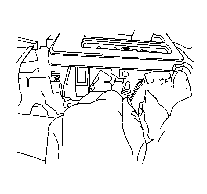
- Remove the manual selector cover illumination lamp bulb socket from the cover.
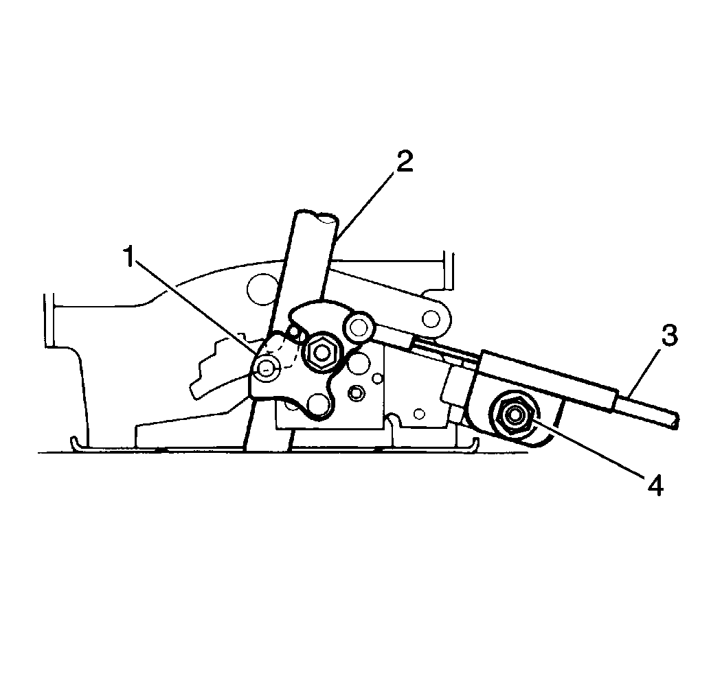
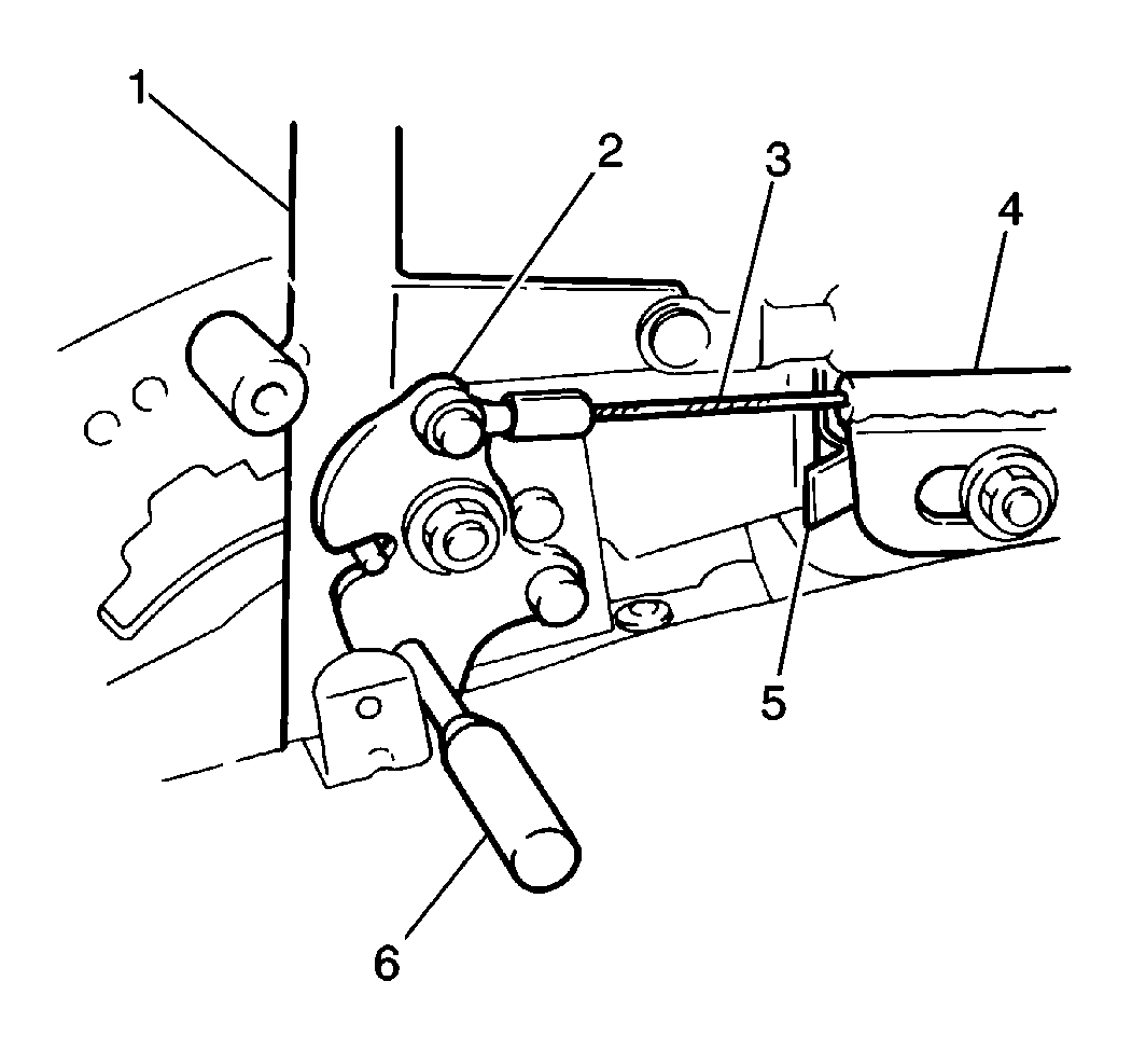
- Remove the interlock cable bolt (4).
- Remove the interlock cable (3) from the selector lever (2) housing bracket.
- Remove the front carpet retainers and pull back the front carpet.
- Remove the 5 screws and the upper and lower steering column covers.
- Remove the lower steering column. Refer to Steering Column Replacement in Steering Wheel and Column.
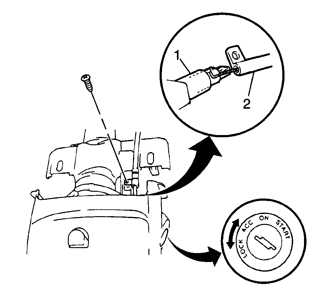
- Remove one screw and the interlock cable (2) retaining clamp from the ignition switch.
- Push the release shaft (1) in at the ignition switch lock mechanism.
- Remove the cable end from the ignition switch and the interlock cable assembly from the vehicle.
Installation Procedure
- Install the interlock cable (2) into the vehicle and route it up to the ignition switch.
- Push the release shaft (1) in at the ignition switch and insert the cable end.
- Install the interlock cable retaining clamp to the ignition switch. Secure the clamp with one screw.
- Reposition and secure the steering column. Refer to Steering Column Replacement in Steering Wheel and Column.
- Install the upper and lower steering column covers. Secure the covers with 5 screws.
- Refit and position the front carpet. Secure the carpet with front carpet retainers.
- Install the interlock cable to the selector lever housing bracket.
- Finger tighten the interlock cable bolt (4).
- Install the interlock cable (3) end into the key release plate (1).
- Move the selector lever to the P position and hold the selector button in.
- Rotate the key release plate (2) and insert a small screwdriver (6) through the key release plate in order to hold the plate in position.
- Allow the retaining spring (5) to position the interlock cable (3) into the bracket (4).
- Install the manual selector cover to the selector lever. Secure the cover with 4 screws.
- Install the manual selector cover illumination lamp bulb socket to the cover.
- Install the selector lever knob to the selector lever. Secure with 2 screws.
- Install the rear console into the vehicle.
- Install the center into the vehicle.
- Install the 6 screws into the console (1,2,3,4,5,6).


Notice: Use the correct fastener in the correct location. Replacement fasteners must be the correct part number for that application. Fasteners requiring replacement or fasteners requiring the use of thread locking compound or sealant are identified in the service procedure. Do not use paints, lubricants, or corrosion inhibitors on fasteners or fastener joint surfaces unless specified. These coatings affect fastener torque and joint clamping force and may damage the fastener. Use the correct tightening sequence and specifications when installing fasteners in order to avoid damage to parts and systems.
Tighten
Tighten the interlock cable bolt to 13 N·m (115 lb in).
Important: After tightening the interlock cable bolt, set the shift selector lever (1) to the P position. Verify that the ignition switch can be turned from the ACC to the LOCK position and that the ignition key can be removed from the ignition switch. With the shift selector lever in any position other than P, verify also that the ignition switch CANNOT be turned from the ACC to the LOCK position.

