Removal Procedure
- Remove the wheel drive shaft. Refer to Wheel Drive Shaft Replacement .
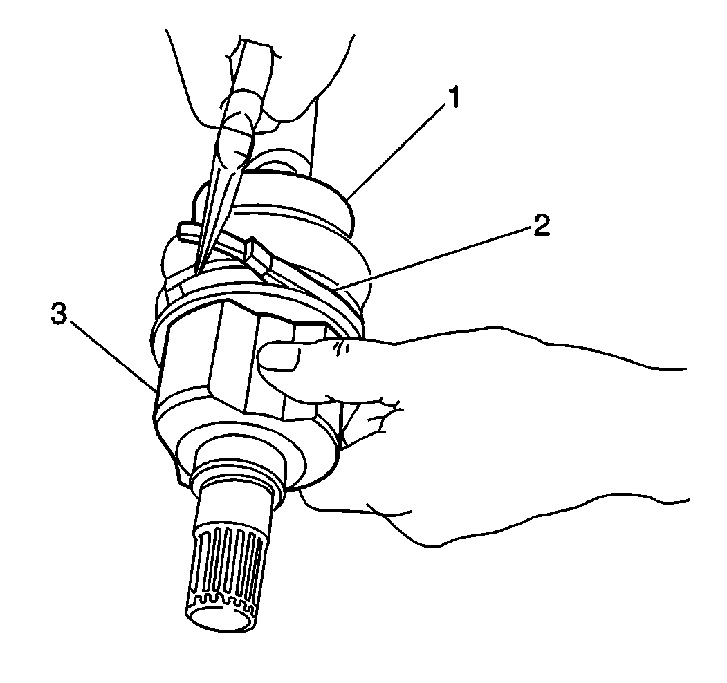
- Place an index mark (reference mark) (3) on the inner joint (1) and the wheel drive shaft (2) to ensure correct assembly.
- Remove the inner boot band (2) from the inner boot (1).
- Remove the outer boot band from the inner boot.
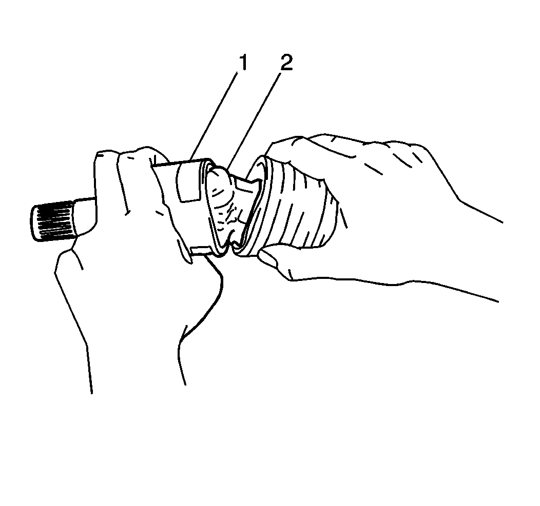
- Remove the inner joint housing (1) from the Tri-Pot joint spider (2).
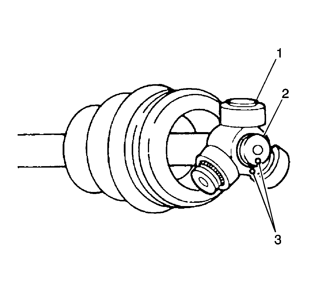
- Place an index mark (reference mark) (3) on the Tri-Pot joint spider (1) and the wheel drive shaft (2) to ensure correct assembly.
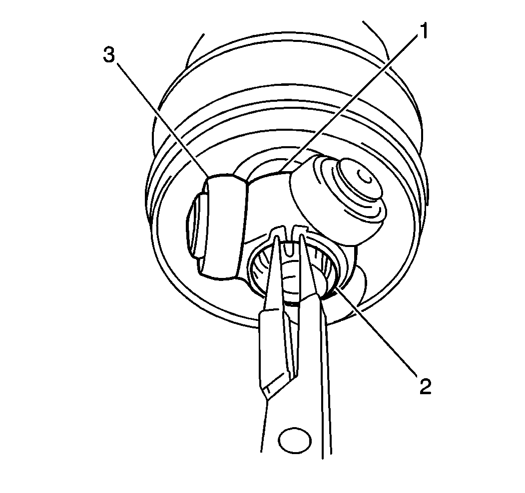
- Remove the snap ring (2) from the wheel drive shaft.
- Remove the Tri-Pot joint spider (1) from the wheel drive shaft.
- Remove the boot from the wheel drive shaft.
- Clean the inner boot with a clean, dry, solvent-free cloth.
- Clean the Tri-Pot joint spider with a clean, dry solvent-free cloth.
- Inspect the inner boot for tears, damage or fatigue. Replace as necessary.
- Inspect the Tri-Pot joint spider for excessive wear or damage. If any excessive wear, damage or abnormality is found, replace the Tri-Pot joint as an assembly.
Notice: Do not overextend the wheel drive shaft. Allowing the inboard joint to overextend can cause separation of the internal components and lead to joint failure.

Notice: When servicing the wheel drive shaft(s), place reference marks on all components to ensure that all components are reassembled in the correct position. If the components are not reassembled in the correct position, premature wear of the joint and/or excessive driveline vibrations may occur.
Notice: Wheel drive shaft boots, seals and clamps should be protected from sharp objects any time service is performed on or near the wheel drive shaft(s). Damage to the boot(s), the seal(s) or the clamp(s) may cause lubricant to leak from the joint and lead to increased noise and possible failure of the wheel drive shaft.


Notice: Do not clean the wheel drive shaft boot(s) in solvent. Cleaning the wheel drive shaft boot(s) in degreaser or other solvents can cause the boot(s) to deteriorate. Use only a clean, dry, solvent-free cloth to clean the wheel drive shaft boot(s).
Notice: Do not wash the Tri-Pot joint spider in solvent or degreaser. Washing the Tri-Pot joint spider in solvent or degreaser will remove all of the lubrication in the spider's needle bearings. Use only a clean, dry, solvent-free rag to clean the Tri-Pot spider assembly.
Important: Do not disassemble the wheel-side joint. If any abnormality is found in the joint, replace it as an assembly. If any abnormality is found in the double offset joint components, the double offset joint must be replaced as an assembly.
Installation Procedure
- Install the inner boot onto the wheel drive shaft.
- Install the inner shaft boot band (3) onto the inner boot (2).
- Install the Tri-Pot joint spider (1) onto the wheel drive shaft (2) aligning the reference marks (3) made during disassembly.
- Secure the spider with the Tri-Pot joint spider snap ring.
- Pack the inner joint housing with 80 to 100 g (2.8 to 3.5 oz) of the lubricant provided in the Tri-Pot joint boot kit.
- Install the inner joint housing (2) onto the Tri-Pot joint spider.
- Install the inner boot band onto the inner boot.
- Inspect both boots for distortion or dents. Correct by pulling outward on the boot in the desired areas until all boot deformation is corrected.
- Install the wheel drive shaft. Refer to Wheel Drive Shaft Replacement .


