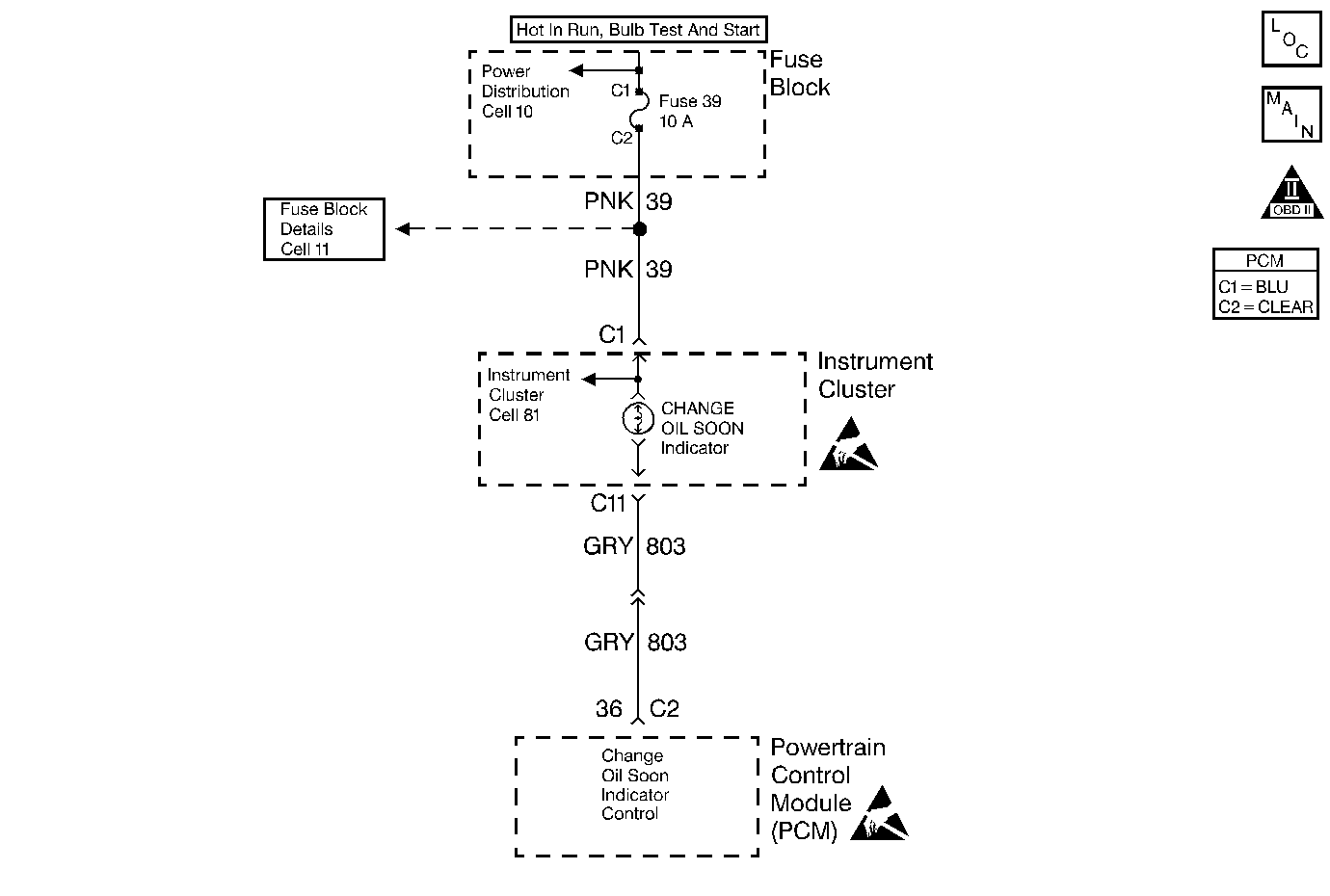
Circuit Description
The Change Oil Soon indicator is powered through a 10 Amp fuse in the fuse block. The PCM turns on indicator by supplying a path to ground through the PCM.
Conditions for Setting the DTC
A PCM controlled lamp on at all times most likely indicates that a condition is present which requires the attention of the vehicle operator.
Check for the following conditions:
| • | Poor connection at PCM. Inspect harness connectors for backed out terminals, improper mating, broken locks, improperly formed or damaged terminals, and poor terminal to wire connection. |
| • | Damaged harness. Inspect the wiring harness for damage. If the harness appears to be OK, disconnect the PCM and turn the ignition on. Observe a voltmeter connected to the affected PCM output circuit while moving connectors and wiring harnesses related to the PCM output circuit. A change in voltage will indicate the location of the fault. |
Action Taken When the DTC Sets
| • | The PCM will not illuminate the malfunction indicator lamp (MIL). |
| • | The PCM will store conditions which were present when the DTC set as Failure Records data only. This information will not be stored as Freeze Frame data. |
Conditions for Clearing the MIL/DTC
| • | A History DTC will clear after 40 consecutive warm-up cycles have occurred without a malfunction. |
| • | The DTC can be cleared by using the scan tool Clear Info function. |
Diagnostic Aids
A PCM controlled lamp on at all times most likely indicates that a condition is present which requires the attention of the vehicle operator.
Check for the following conditions:
| • | Poor connection at PCM. Inspect harness connectors for backed out terminals, improper mating, broken locks, improperly formed or damaged terminals, and poor terminal to wire connection. |
| • | Damaged harness. Inspect the wiring harness for damage. If the harness appears to be OK, disconnect the PCM and turn the ignition on. Observe a voltmeter connected to the affected PCM output circuit while moving connectors and wiring harnesses related to the PCM output circuit. A change in voltage will indicate the location of the fault. |
Test Description
Number(s) below refer to the step number(s) on the Diagnostic Table:
-
Normally, ignition feed voltage should be present on the output control circuit with the PCM disconnected and the ignition turned ON.
-
Checks for a shorted component or a short to battery positive voltage on the output control circuit. Either condition would result in a measured current of over 500 milliamps. Also checks for a component that is going open while being operated, resulting in a measured current of 0 milliamps.
-
Checks for a short to voltage on the lamp control circuit.
-
This vehicle is equipped with a PCM which utilizes an Electrically Erasable Programmable Read Only Memory (EEPROM). When the PCM is being replaced, the new PCM must be programmed. Refer to Powertrain Control Module Replacement/Programming .
Step | Action | Value(s) | Yes | No |
|---|---|---|---|---|
1 | Was the Powertrain On Board Diagnostic (OBD) System Check performed? | -- | ||
2 | Was the Instrument Cluster System check in Electrical Diagnosis performed? | -- | Go to Instrument Cluster System Check in Instrument Panel, Gauges and Console | |
Is voltage near the specified value? | B+ | |||
Does the current reading remain between the specified values? | 0.05 -0.5 Amp (50-500 mA) | |||
Is voltage at the specified value? | 0.0V | |||
6 | Locate and repair the short to voltage in the affected PCM output circuit. Refer to Wiring Repairs in Wiring Systems. Did you complete the repair? | -- | -- | |
7 | Check the ignition feed fuse for the instrument panel cluster indicator lamps. Is the the fuse blown? | -- | ||
8 |
Did you complete the repair? | -- | -- | |
9 |
Is the voltage near the specified value? | B+ | ||
10 |
Was a problem found? | -- | ||
11 |
Was a problem found? | -- | ||
12 |
Does the test light flash ON and OFF? | -- | Go to Diagnostic Aids | |
13 |
Was a problem found? | -- | ||
14 | Locate and repair open in the ignition feed circuit to the instrument panel cluster indicator lamps. Refer to Wiring Repairs in Wiring Systems. Did you complete the repair? | -- | -- | |
15 | The fault is isolated to the instrument panel cluster. Refer to Instrument Cluster System Check in Instrument Panel, Gauges, and Console. Did you complete the repair? | -- | -- | |
|
Important: : The replacement PCM must be programmed. Replace the PCM. Refer to Powertrain Control Module Replacement/Programming . Did you complete the repair? | -- | -- | ||
17 | Operate the affected lamp using the scan tool output tests function. Does the affected lamp operate properly? | -- | System OK |
