Cylinder Head Replacement Left Front
Special Tools
J 36660-A Electronic Torque Angle Meter
Removal Procedure
- Perform an engine compression and leak down test. Refer to Engine Compression Test and Cylinder Leakage Test .
- Raise and suitably support the vehicle. Refer to Lifting and Jacking the Vehicle .
- Drain the engine coolant from the cooling system. Refer to Cooling System Draining and Filling .
- Drain the engine oil. Refer to Engine Oil and Oil Filter Replacement .
- Lower the vehicle.
- Remove the upper intake manifold. Refer to Intake Manifold Replacement .
- Remove the valve rocker arm covers.
- Remove the lower intake manifold. Refer to Intake Manifold Replacement .
- Remove the valve rocker arms and pushrods. Refer to Valve Rocker Arm and Push Rod Replacement .
- Remove the exhaust crossover pipe. Refer to Exhaust Crossover Replacement .
- Remove the right engine mount strut bracket. Refer to Engine Mount Strut Bracket Replacement .
- Remove the oil level indicator tube. Refer to Oil Level Indicator and Tube Replacement .
- Remove the left (front) spark plug wires from the spark plugs. Refer to Spark Plug Wire Harness Replacement .
- Remove the left (front) spark plugs. Refer to Spark Plug Replacement .
- Remove the left (front) exhaust manifold. Refer to Exhaust Manifold Replacement .
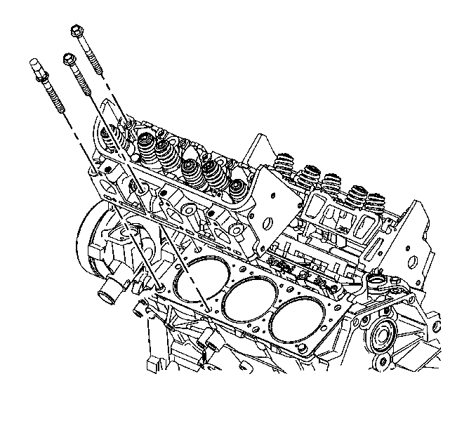
- Remove and discard the left (front) cylinder head bolts.
- Remove the left (front) cylinder head.
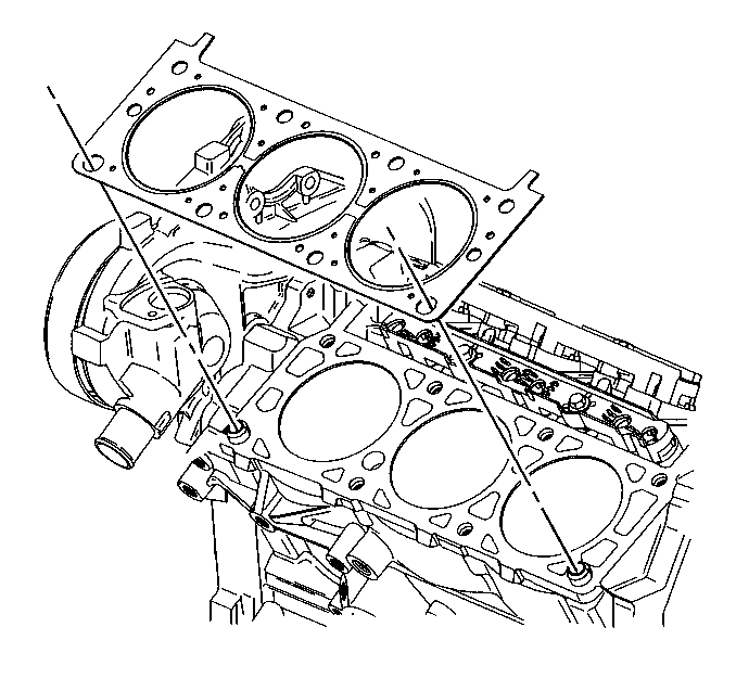
- Remove the left (front) cylinder head gasket.
- Clean the following areas:
| • | The gasket sealing surfaces on the cylinder head, cylinder block, and intake manifolds. |
| • | The cylinder block bolt threads. |
Installation Procedure
- Install a new left (front) cylinder head gasket.
- Install the left (front) cylinder head over the locator pins and over the gasket.
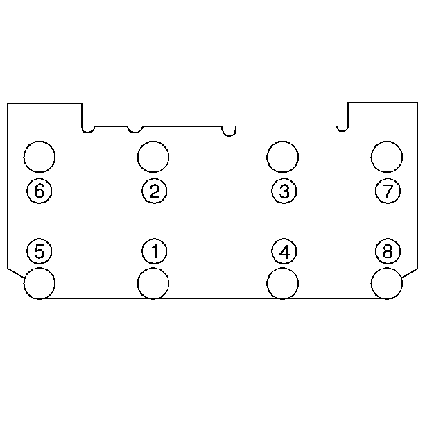
- Tighten the left (front) cylinder head bolts (1-8) in sequence.
- Install the left (front) exhaust manifold. Refer to Exhaust Manifold Replacement .
- Install the left (front) spark plugs. Refer to Spark Plug Replacement .
- Install the left (front) spark plug wires to the spark plugs. Refer to Spark Plug Wire Harness Replacement .
- Install the oil level indicator tube. Refer to Oil Level Indicator and Tube Replacement .
- Install the right engine mount strut bracket. Refer to Engine Mount Strut Bracket Replacement .
- Install the exhaust crossover pipe. Refer to Exhaust Crossover Replacement .
- Install the valve rocker arms and pushrods. Refer to Valve Rocker Arm and Push Rod Replacement .
- Install the lower intake manifold. Refer to Intake Manifold Replacement .
- Install the valve rocker arm covers.
- Install the upper intake manifold. Refer to Intake Manifold Replacement .
- Fill the engine with new engine oil. Refer to Engine Oil and Oil Filter Replacement .
- Fill the cooling system with engine coolant. Refer to Cooling System Draining and Filling .


Notice: Refer to Fastener Notice in the Preface section.
Notice: This component uses torque-to-yield bolts. When servicing this component do not reuse the bolts, New torque-to-yield bolts must be installed. Reusing used torque-to-yield bolts will not provide proper bolt torque and clamp load. Failure to install NEW torque-to-yield bolts may lead to engine damage.
Tighten
| • | Tighten the cylinder head bolts (1-8) in sequence to 60 N·m (44 lb ft). |
| • | Use the J 36660-A in order to turn the cylinder head bolts (1-8) in sequence an additional 95 degrees. |
Cylinder Head Replacement Right Rear
Special Tools
J 36660-A Electronic Torque Angle Meter
Removal Procedure
- Perform an engine compression and leak down test. Refer to Engine Compression Test and Cylinder Leakage Test .
- Raise and suitably support the vehicle. Refer to Lifting and Jacking the Vehicle .
- Drain the engine coolant from the cooling system. Refer to Cooling System Draining and Filling .
- Drain the engine oil. Refer to Engine Oil and Oil Filter Replacement .
- Lower the vehicle.
- Remove the upper intake manifold. Refer to Intake Manifold Replacement .
- Remove the valve rocker arm covers.
- Remove the lower intake manifold. Refer to Intake Manifold Replacement .
- Remove the valve rocker arms and pushrods. Refer to Valve Rocker Arm and Push Rod Replacement .
- Remove the exhaust crossover pipe. Refer to Exhaust Crossover Replacement .
- Remove the right (rear) spark plug wires from the spark plugs. Refer to Spark Plug Wire Harness Replacement .
- Remove the fuel line bracket. Refer to Engine Controls - 3.1L.
- Remove the generator brace. Refer to Generator Brace Replacement in Engine Electrical.
- Remove the right (rear) spark plugs. Refer to Spark Plug Replacement .
- Remove the right (rear) exhaust manifold. Refer to Exhaust Manifold Replacement .
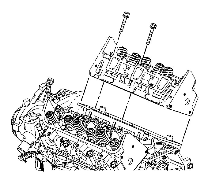
- Remove and discard the right (rear) cylinder head bolts.
- Remove the right (rear) cylinder head.
- Remove the right (rear) cylinder head gasket.
- Clean the following areas:
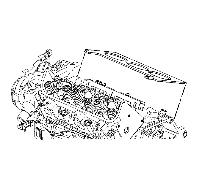
| • | The gasket sealing surfaces on the cylinder head, cylinder block, and intake manifolds. |
| • | The cylinder block bolt threads. |
Installation Procedure
- Install a new right (rear) cylinder head gasket.
- Install the right (rear) cylinder head over the locator pins and over the gasket.
- Tighten the right (rear) cylinder head bolts (1-8) in sequence.
- Install the right (rear) exhaust manifold. Refer to Exhaust Manifold Replacement .
- Install the right (rear) spark plugs. Refer to Spark Plug Replacement .
- Install the right (rear) spark plug wires to the spark plugs. Refer to Spark Plug Wire Harness Replacement .
- Install the generator brace. Refer to Generator Brace Replacement in Engine Electrical.
- Install the fuel line bracket. Refer to Engine Controls - 3.1L.
- Install the exhaust crossover pipe. Refer to Exhaust Crossover Replacement .
- Install the pushrods and valve rocker arms. Refer to Valve Rocker Arm and Push Rod Replacement .
- Install the lower intake manifold. Refer to Intake Manifold Replacement .
- Install the valve rocker arm covers.
- Install the upper intake manifold. Refer to Intake Manifold Replacement .
- Fill the engine with new engine oil. Refer to Engine Oil and Oil Filter Replacement .
- Fill the cooling system with engine coolant. Refer to Cooling System Draining and Filling .


Notice: Refer to Fastener Notice in the Preface section.

Notice: This component uses torque-to-yield bolts. When servicing this component do not reuse the bolts, New torque-to-yield bolts must be installed. Reusing used torque-to-yield bolts will not provide proper bolt torque and clamp load. Failure to install NEW torque-to-yield bolts may lead to engine damage.
Tighten
| • | Tighten the cylinder head bolts (1-8) in sequence to 60 N·m (44 lb ft). |
| • | Use the J 36660-A in order to turn the cylinder head bolts (1-8) in sequence an additional 95 degrees. |
